My install of 28 inch 145W LED Bar (14k lumen)

RysiuM

New member
My install of 28 inch 145W LED Bar (14k lumen) and Accessory Fuse Box (with pictures)

Like I wrote in my thread "My version of Interior LED lights" I decided to add more LED to my 4R. I bought 28 inch LED bar of Ebay. There were few selling points for me (besides the price):
- It is exactly 725mm long (28.5inch) so it will fit behind upper grill without any cuts.
- It mounts from the bottom (not from sides) so all the width is used for light, not mounting.
- The bottom mounts are very low, so I can mount it to original metal plate behind the grill.
- It uses lenses instead of reflectors so the focus is really good.

No false claims about the light output from this seller (US located) and the real measured power (145W at 12V) is quite close to advertised 180W. I don't expect magic, but from calculations I think it will give around 14k lumens.

Of course I can't say anything about durability or water resistance - time will tell. The whole lamp looks quite solid and rust proof - all parts are either aluminum or stainless steel. The lamp came with wire harness which I will salvage for parts as I want clean "factory like" installation - similar to what I did with OSRAM LEDFOG101. But that will be later. For now the mechanical installation.

So here is what I saw on Ebay before I put my money on:
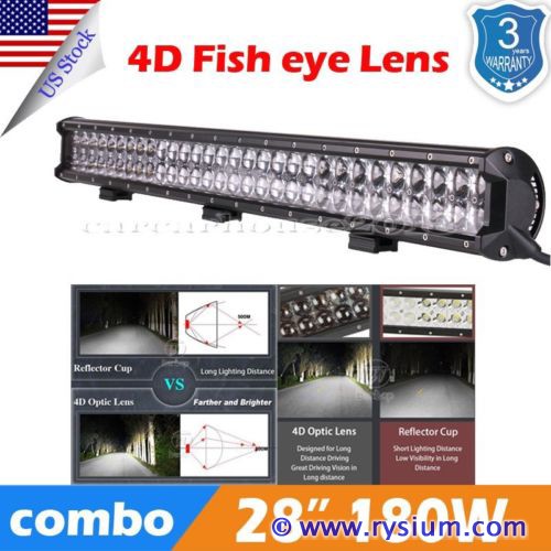
4Runner-Ledbar-01.jpg


And this is the real thing on garage floor just before the installation
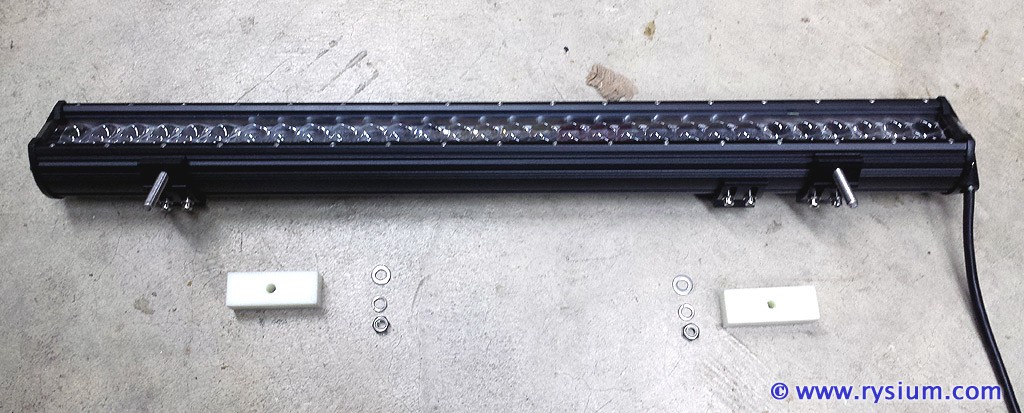
4Runner-Ledbar-03.jpg


Step 1 - Mechanical installation

I like the way this lamp is mounted. There are three metal "sliders" screwed to the lamp case via two M5 bolts each. The slider can be bolted to a car with 1 M8 bolt each. Of course all bolts, nuts and washers are stainless steel.
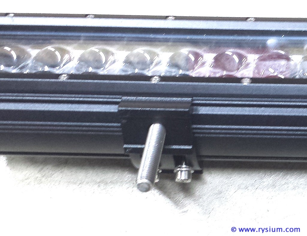
4Runner-Ledbar-02.jpg


This mounting puts the lamp very close to the mounting base, so lamp will fit below Toyota emblem.

I drilled two 8mm holes in grill bracket (the third slider will not be used) one on each side.
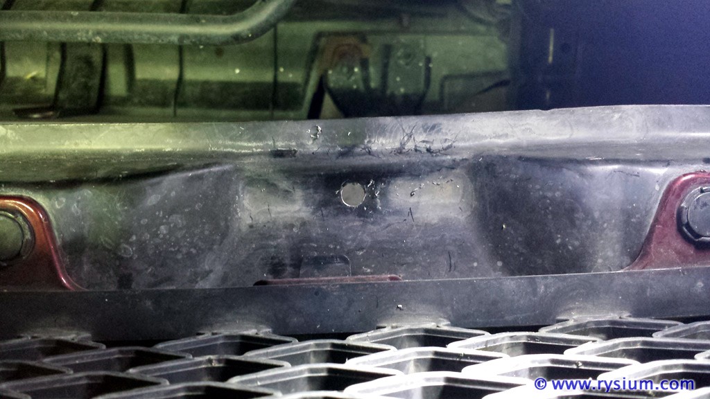
4Runner-Ledbar-04.jpg


Because this brill bracket was actually lower than I expected so I replaced M8 bolts with new, longer ones and I made 2 derlin spacers. I know that they are ugly white, but they are hidden between slider and the grill bracket and nobody will ever see them there.
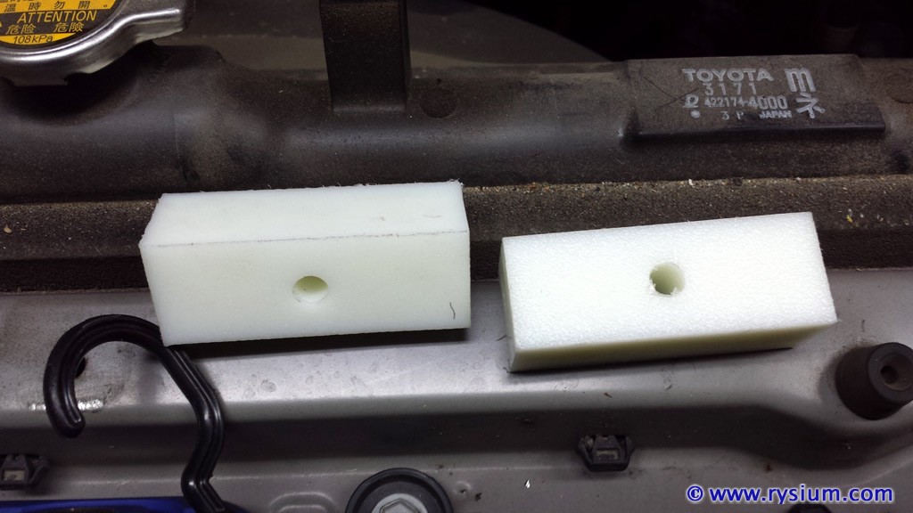
4Runner-Ledbar-07.jpg


Now lamp is bolted to the grill bracket with lock washer and nylon insert nut. Just to be sure it does not vibrate loose.
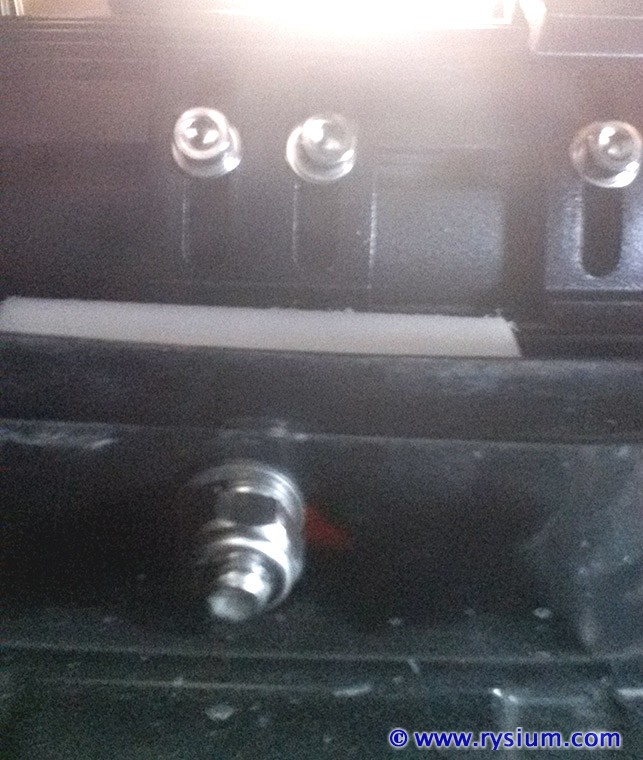
4Runner-Ledbar-05.jpg


Looking from the top is nicely hidden behind the grill out of the way leaving still a lot of space between the grill and radiator if I need to do something there. Notice on the picture, the lamp takes all the width of the upper grill all the way to the air ducts. 30 inch light bar would not fit there without cutting air ducts.
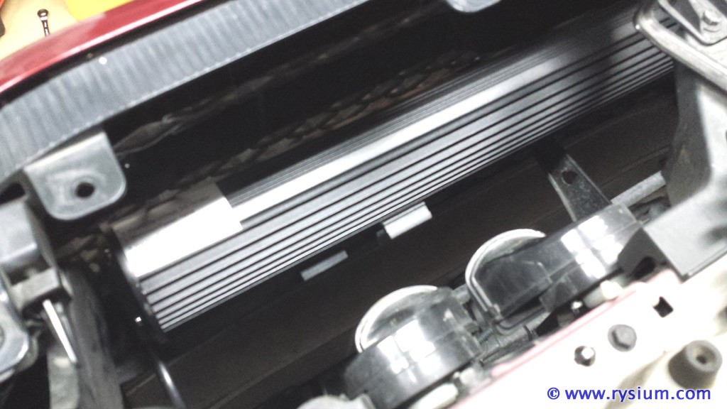
4Runner-Ledbar-06.jpg


Actually because the lamp is one big block of aluminum it enforced the grill bracket so it feel much sold now. Lamp aligning screws are easy accessible from behind so it will make the aiming process very easy.

So the only alteration to the truck was drilling two 8mm holes in metal grill bracket. Other than that the installation is 100% reversible a and took me about an hour to complete. I know I will loose some light that is blocked by Toyota emblem at the center, but I have 14000 lumens to spare, so if I get only 12000 I will still be very happy.

Here is the picture of the light bar installed and how it looks from the outside. Actually it doesn't look at all as it is hardly visible. But anyway here are these closeup pictures:
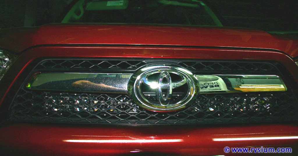
4Runner-Ledbar-08.jpg


4Runner-Ledbar-09.jpg


This concludes step 1 - Mechanical installation

Now the electrical installation is the next step. To be continued...
 
Last edited:
Register to hide this ad
This is an awesome write up.

Your mounting technique was great using those sliders. I wish all bars came with that mounting style.

I just wanted to add that you say in your post you can't get anything bigger than 30" without cutting those air dams, but that's not entirely true. I have a 32" LED bar in the same location, and didn't have to cut anything. A few other members on here have done the same as well.
 
This is an awesome write up.

Thank you.

I just wanted to add that you say in your post you can't get anything bigger than 30" without cutting those air dams, but that's not entirely true. I have a 32" LED bar in the same location, and didn't have to cut anything. A few other members on here have done the same as well.

You are correct, I should have not generalized. In 2012 SR5 models the upper grill width is about 32 inch but the plastic ducts are taking about 1 inch or so on each end. I saw write-ups from members putting 32 inch lamp but one was by trimming air ducts, the other was different grill (Trail maybe?). Anyway from the last picture you can see about 3/4 inch between lamp body and the air duct.

Now back to my project.

Step 2 - Underhood Accessory Fuse Box installation.

Unfortunately all cars are built as cheap as possible so even there are many empty slots in the original under the hood fuse box , the connecting wires are not there. Looks like manufactures don't want us to improve their products.

So I will have to add my own fuse box. I was looking for people's solutions, and really I liked [MENTION=65614]Antman[/MENTION] "UNDERHOOD ACCESSORY FUSE BOX INSTALL". I mean the location is perfect - close to the cabin, battery and enough room for nice fuse box. The only thing I did not like was quite long hot wire between the battery and 100A fuse, and lack of "mud-splash" protection. I mean nothing is there waterproof, but I would like to keep fuses clean from dust and mud, that might get under the hood.

So still giving a lot of credits to [MENTION=65614]Antman[/MENTION] here is my custom Under the Hood Accessory Fuse Box.

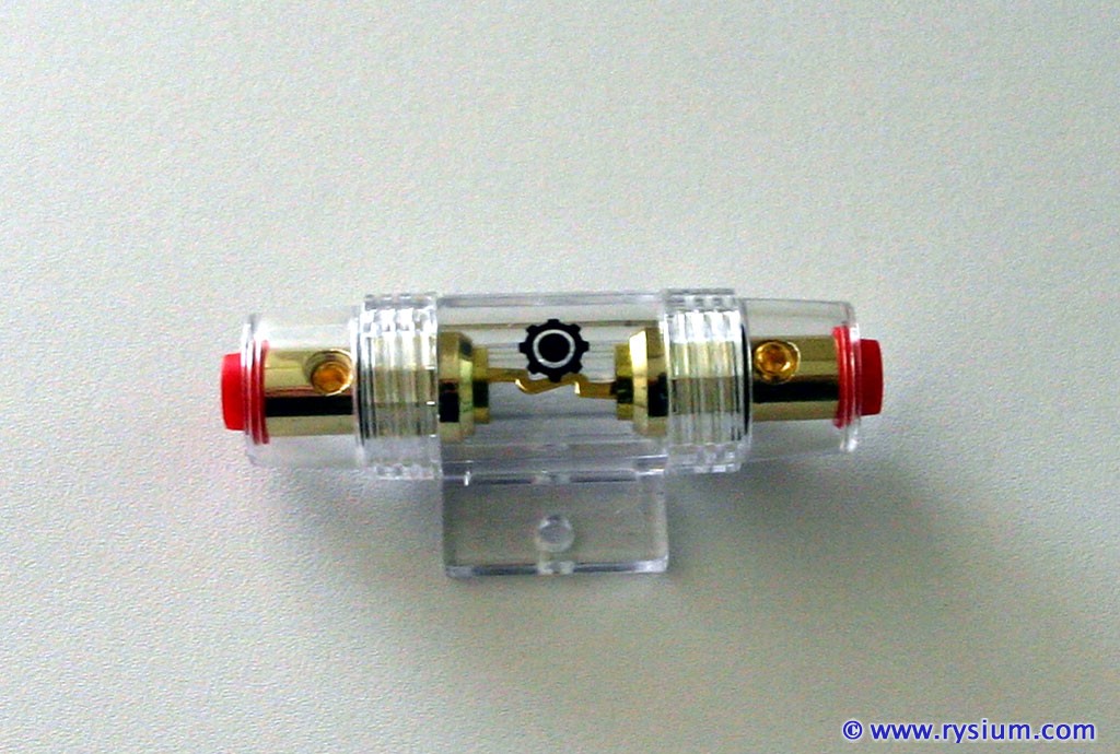
The main 100A fuse (actually I used 80A fuse, not planing to get more than 1000W from the battery) is "InstallGear 4/8/10 Gauge AWG In-Line AGU Fuse Holder with 80 Amp Fuse" from Amazon Prime ($5.45)

4Runner-Fusebox-01.jpg


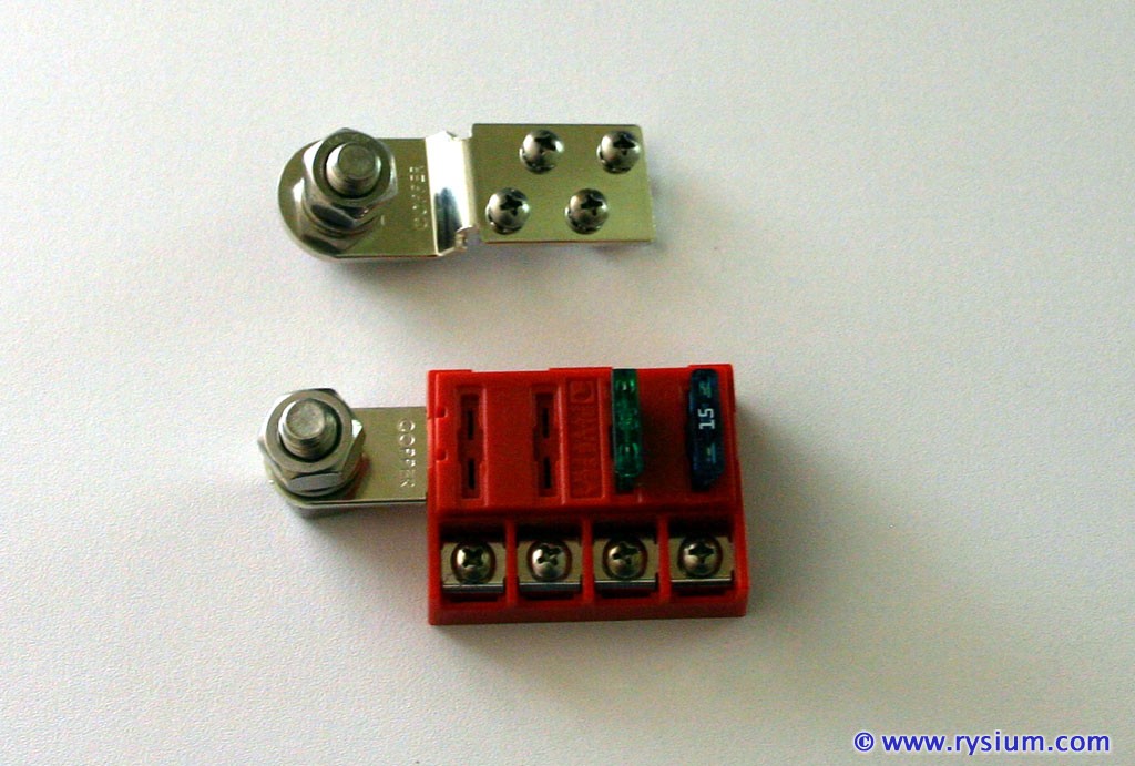
Main distribution 4 x 30A is "Blue Sea Systems ST-Blade Battery Terminal Mount Fuse Block Kit" from Ebay ($28.23 including CA tax)

4Runner-Fusebox-02.jpg


This kit comes with one 10A fuse and 4 x ground connector. So my fuse box will provide +12V and ground if needed. I can use 10A fuse for hood lamp, maybe. The LED bar takes about 10Amps at 12V and in provided harness it had 30A fuse. I think I will protect the circuit by 20A fuse - should be enough.


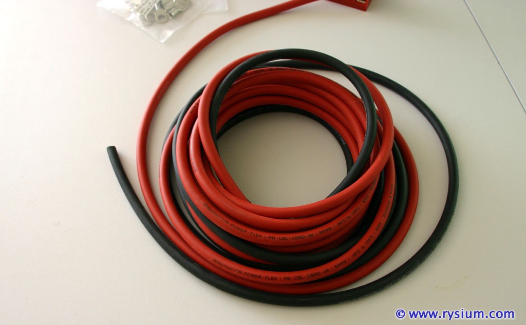
I did not have 100A wires nor terminal contacts around, so I ordered some "Welding Cable Red Black 6 AWG GAUGE COPPER WIRE" 15 ft each color (I will use it some day). This is true copper wire (not aluminum wire tinned with copper) with 263 strands to carry over 100A. Covered by EPDM 600V Operating -50°C to 105°C insulation it makes good "under the hood" material. Flexible yet very strong and durable.

4Runner-Fusebox-04.jpg


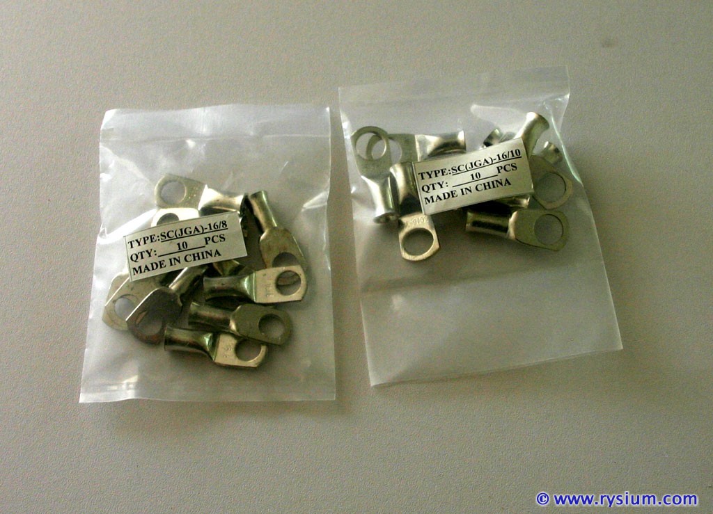
Finally I ordered some "Tinned Copper Cable Lugs Ring Terminals for 6 AWG wire" 10-pack with 8mm eye and 10-pack with 10mm eye.

4Runner-Fusebox-03.jpg


Of course two M10 stainless steel bolts, washers and nuts for "Battery Terminal connectors" in fuse block kit and one stainless steel M8 bolt and washer for connecting ground wire to car body.

Now have all parts, so it's time do do some work. To be continued...
 
Last edited:
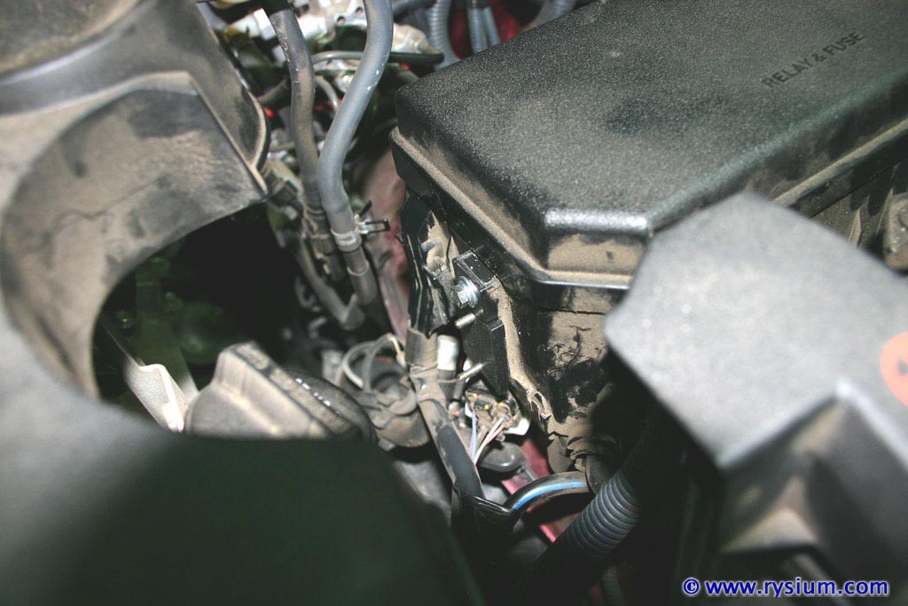
First was finding a place for quite big 100A fuse holder. I mean this thing is huge. OK, 100A is a lot of current so probably it needs to be that big :wink2:. On the engine side of the original fuse box there is a slot with a hole. I don't know what Toyota designed it for, but in my SR5 it is for noting, or should I say it is just for my 100A fuse holder :thumb:. Thank you Toyota for that.

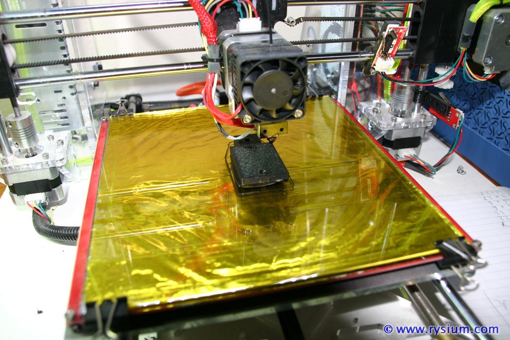
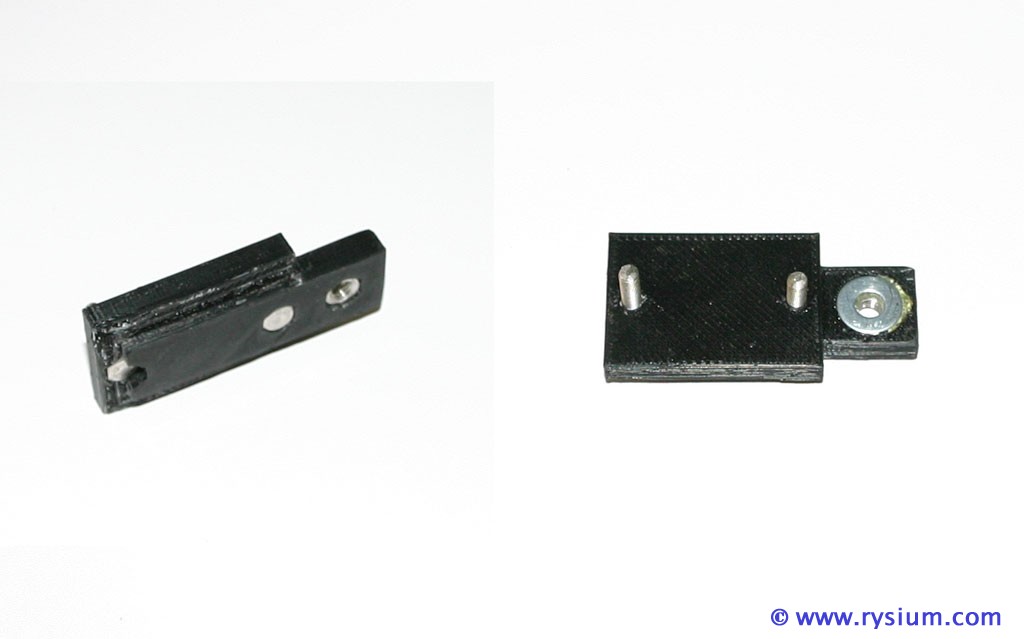
The only thing I need was something that on one side will fit that slot, and on the other side will have two screws so I can put the fuse holder on. After some measuring and a bit of work with Open SCAD software I ended up with a bracket ready to be printed on my 3D printer.

4Runner-Fusebox-05.jpg


I printed it in black ABS, put some stainless steel bolts, nuts and washers and here is my bracket

4Runner-Fusebox-06.jpg


It fits in the space provided by Toyota, like it as made by Toyota R&D

4Runner-Fusebox-07.jpg


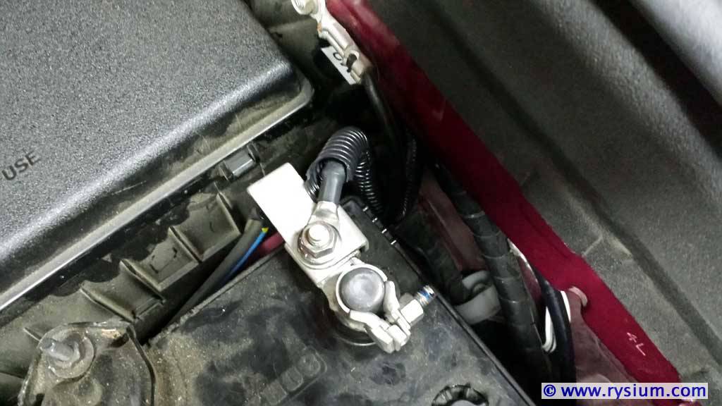
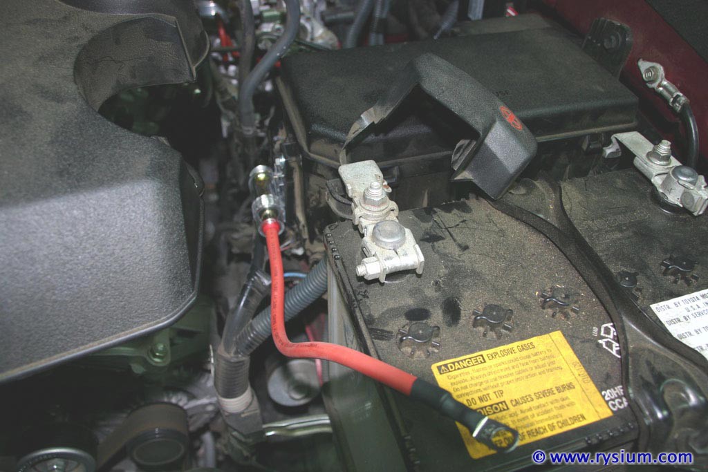
Here is the picture of fuse holder with battery side wire mounted. The terminal will be screwed under the original battery connector. Should be solid and safe.

4Runner-Fusebox-08.jpg


To be continued....
 
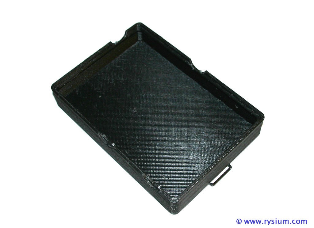
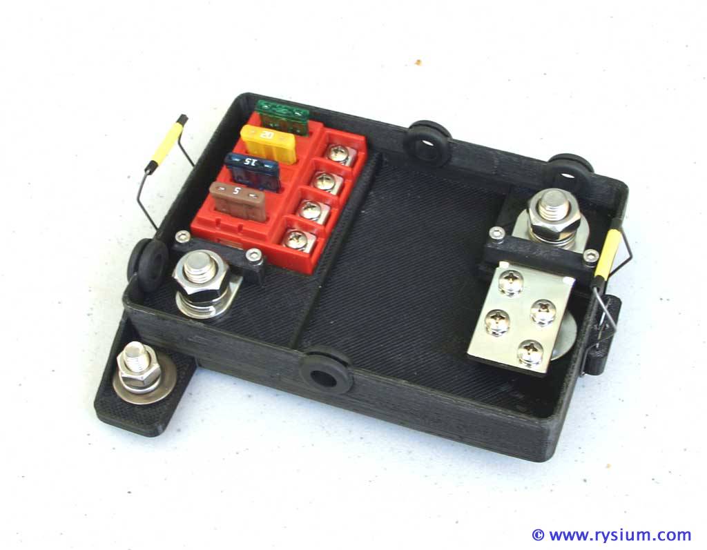
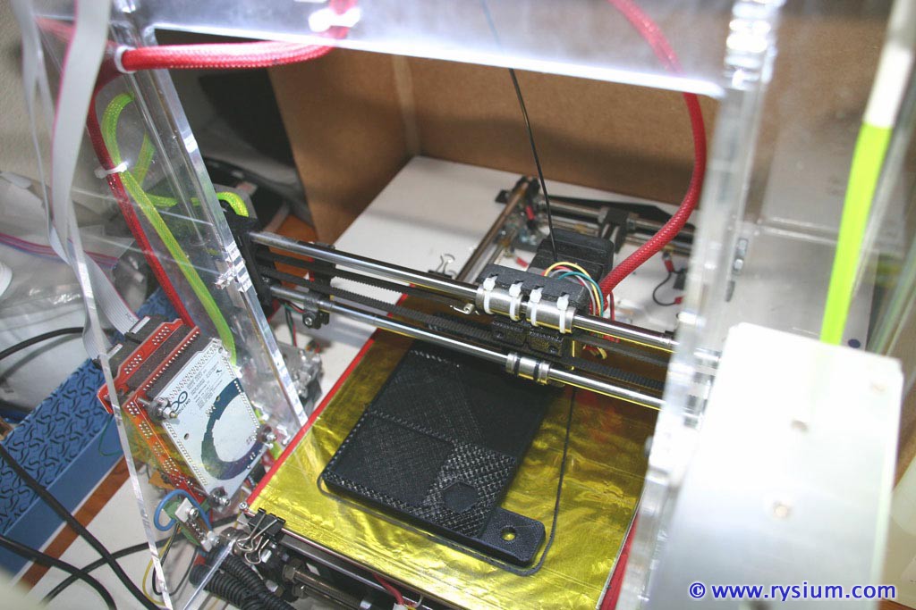
Now the main thing: THE BOX. This one is 100% custom. I designed it in Open SCAD (3D program) and printed in on 3D printer in black ABS. The designing process was not very sophisticated really. First I put a piece of paper in the wheel well then I traced mounting holes and available space for the box. Then I placed Blue Sea Systems Fuse Block elements on that paper and traced them too. Finally I transferred all dimensions to Open SCAD. Then added walls and cutouts for grommets. The design was printing in black ABS for almost 5 hours.

4Runner-Fusebox-09.jpg


Printing big footprint elements in ABS is quite tricky as IBS like to un-stick from the table and warp the shape. I used all known tricks (very hot table, ABS juice over capon tape, printing in closed enclosure) and actually ended up with quite nice box. Here is how it fits into Antman's space

4Runner-Fusebox-10.jpg


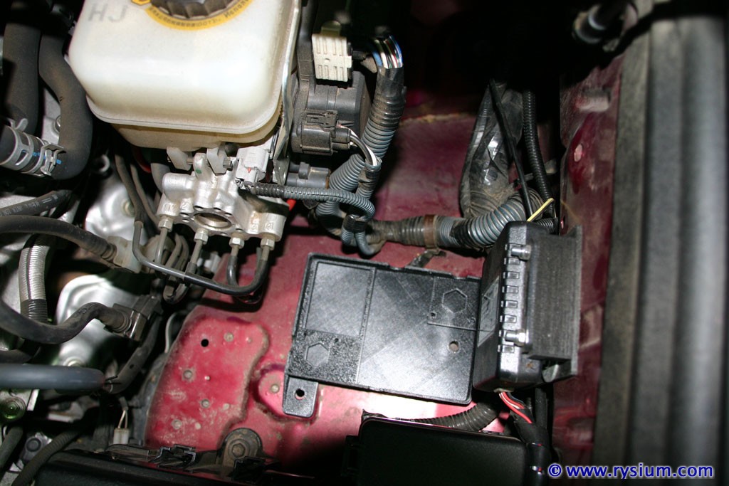
I put both parts of Blue Sea Systems Fuse Block for trial fit and all looks very nice. You can see the box could be a bit longer but I have OSRAM FOG LED Lights controller box mounted to the side.

4Runner-Fusebox-11.jpg


The positive wire will come out from the side towards the engine and will go straight to the 100A inline fuse holder. The negative wire will go towards the cabin and will be bolted to one of the empty threaded M8 holes in the fender.

Individual fused wires will go out of the box in two bundles through grommets towards the cabin or original fuse box. I still need to find a place for LED bar relay. Because it is 40A sealed relay I will probably keep it outside of my custom fuse box.

Now the last part to print is the box cover. I have it already designed and sliced for 3D printing, (should take about 4 hours to print) but first I need to clean clogged printing head, so no pictures yet.

To be continued...
 
Last edited:
Now the main thing: THE BOX. This one is 100% custom. I designed it in Open SCAD (3D program) and printed in on 3D printer in black ABS. The designing process was not very sophisticated really. First I put a piece of paper in the wheel well then I traced mounting holes and available space for the box. Then I placed Blue Sea Systems Fuse Block elements on that paper and traced them too. Finally I transferred all dimensions to Open SCAD. Then added walls and cutouts for grommets. The design was printing in black ABS for almost 5 hours.

4Runner-Fusebox-09.jpg


Printing big footprint elements in ABS is quite tricky as IBS like to un-stick from the table and warp the shape. I used all known tricks (very hot table, ABS juice over capon tape, printing in closed enclosure) and actually ended up with quite nice box. Here is how it fits into Antman's space

4Runner-Fusebox-10.jpg


I put both parts of Blue Sea Systems Fuse Block for trial fit and all looks very nice. You can see the box could be a bit longer but I have OSRAM FOG LED Lights controller box mounted to the side.

4Runner-Fusebox-11.jpg


The positive wire will come out from the side towards the engine and will go straight to the 100A inline fuse holder. The negative wire will go towards the cabin and will be bolted to one of the empty threaded M8 holes in the fender.

Individual fused wires will go out of the box in two bundles through grommets towards the cabin or original fuse box. I still need to find a place for LED bar relay. Because it is 40A sealed relay I will probably keep it outside of my custom fuse box.

Now the last part to print is the box cover. I have it already designed and sliced for 3D printing, (should take about 4 hours to print) but first I need to clean clogged printing head, so no pictures yet.

To be continued...

Great. Now I want a 3D Printer! :) The possibilities for all the mods I have wanted to do on my Camry and Tacoma, and now my Runner... I love ya man, but my wife may want to say angry things to you when I start wanting to throw money into this :)
 
Now I want a 3D Printer! :)...I love ya man, but my wife may want to say angry things to you when I start wanting to throw money into this :)

Print her some nice things - she will love it. I printed other useful stuff that normally are not available. Your imagination (and the printing size) is the limit. :bluejump:
 
Yesterday I fixed my 3D printer (printing head was blocked by some crap) so I started printing the cover. It took almost 4 hours keeping me from going to bed before midnight. I did try this morning how the cover fits the box - looks like it was designed for it - :cheers:.

It is so difficult to take a picture of black object - camera does not show shape with all details, but the surface imperfections are overexposed. In real life the cover looks much nicer. Anyway, the picture taken this morning.

4Runner-Fusebox-12.jpg


To be continued...
 
Last edited:
I printed additional pieces, kind of bard holding both metal poles to the box (pictures later) and tested them to see how they fit. Then I realized that I made a mistake in the design of my box - one grommet hole was not in line with the cable. By positioning the hole I forgot to include thickness of the box wall and offset of Fuse Block in the box. At the same time I did not like the brackets that would hold the cover, so back to drawing board.

Actually I already fixed the design and the second box is printing now - after 8 hours or so I will have both parts.

To be continued...
 
Last edited:
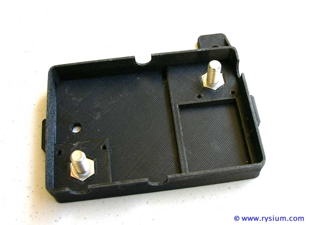
It took the whole afternoon and half of the night to print the new box. This one is perfect. Not only the changes in design made the box working better but for whatever reason the printing quality was better. Here is the the box (new design) with M10 bolts already pressed in

4Runner-Fusebox-15.jpg


On the bottom four M3 nuts pressed in. They are used to bolt in pole holders (printed last day)

4Runner-Fusebox-16.jpg


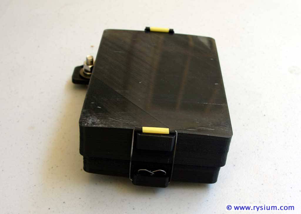
I have made "clip-on" type lock for the cover. It is made form piano wire and plastic tubes (yellow and black) at the top. Nothing complicated, very easy to latch and unlatch with positive locking. The Fuse holder already mounted and pole holders are already in place.

4Runner-Fusebox-17.jpg


This is how the locked box with cover looks like. It is for sure splash proof.

4Runner-Fusebox-18.jpg


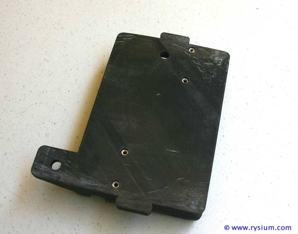
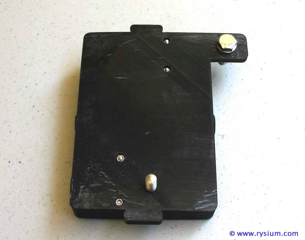
The bottom of the box. Two mounting bolts will be screwed to the top of wheel well.

4Runner-Fusebox-19.jpg


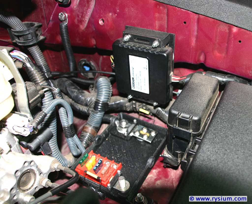
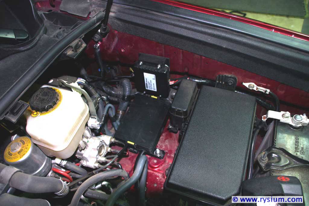
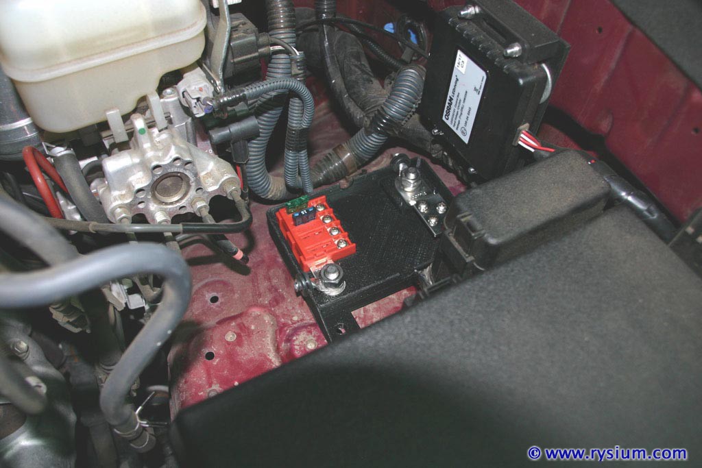
Now the box is mounted on the wheel well and negative pole is already connected. The other end on negative wire is bolted to the one of M8 threaded holes in the inside of the fender. It is visible on the left upper corner of this picture just below the hood airspring mount.

4Runner-Fusebox-20.jpg


EDIT: I decided that it will be much better to connect negative cable directly to the battery the same way positive is connected. This way I don't stress the fender, nut and paint around by running 80A through it.

4Runner-Fusebox-24.jpg


Now the positive pole is connected. The cable is held to the fender with 1/2 inch wire-tie bolted to one of M6 threaded holes in the wheel well. This will prevent any rubbing or wire movement. One of hoses going from the engine is near by and I did not want the cable to touch this hose.

4Runner-Fusebox-21.jpg


Now the box is covered and locked. It looks almost like made by Toyota. I should have printed Toyota logo on it :p.

4Runner-Fusebox-22.jpg


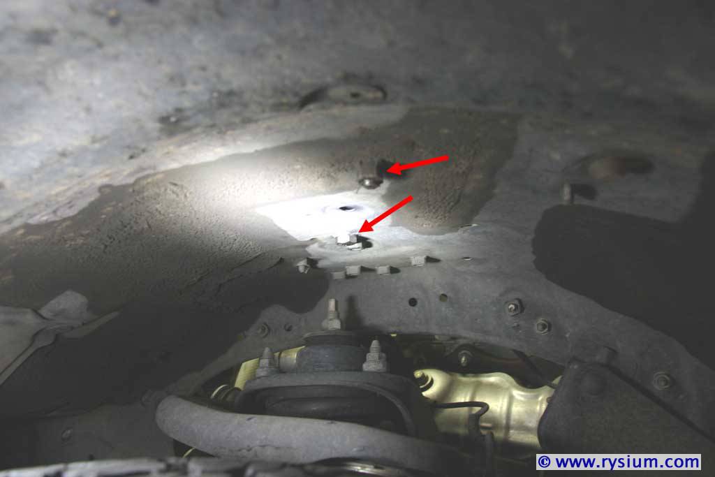
On this picture you can see two bolts mounting the box to the wheel well. The view from the inside of wheel well. Red arrows point to these bolts.

4Runner-Fusebox-23.jpg


This concludes Step 2 - Underhood Accessory Fuse Box installation.

Now going to do "low current" wiring. To be continued...
 
Last edited:
Step 3 - Under the Hood LED Bar Wiring.

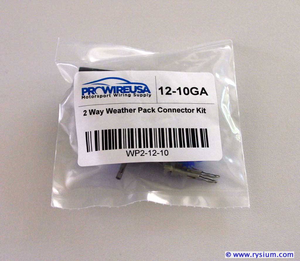
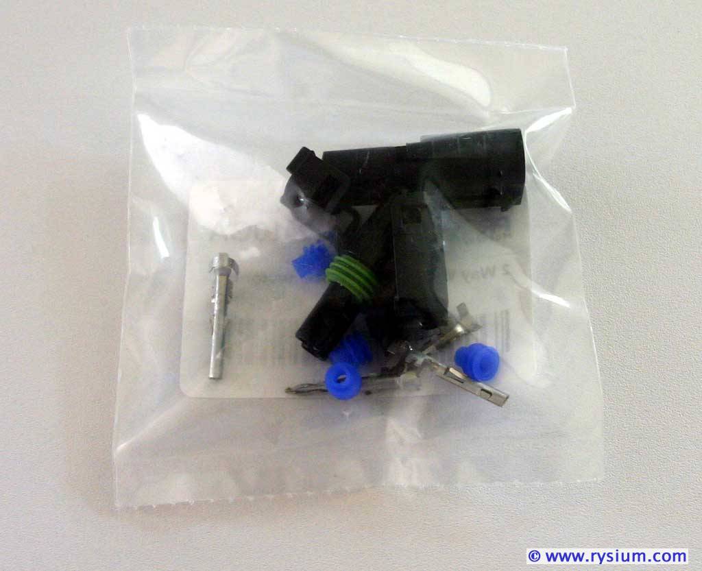
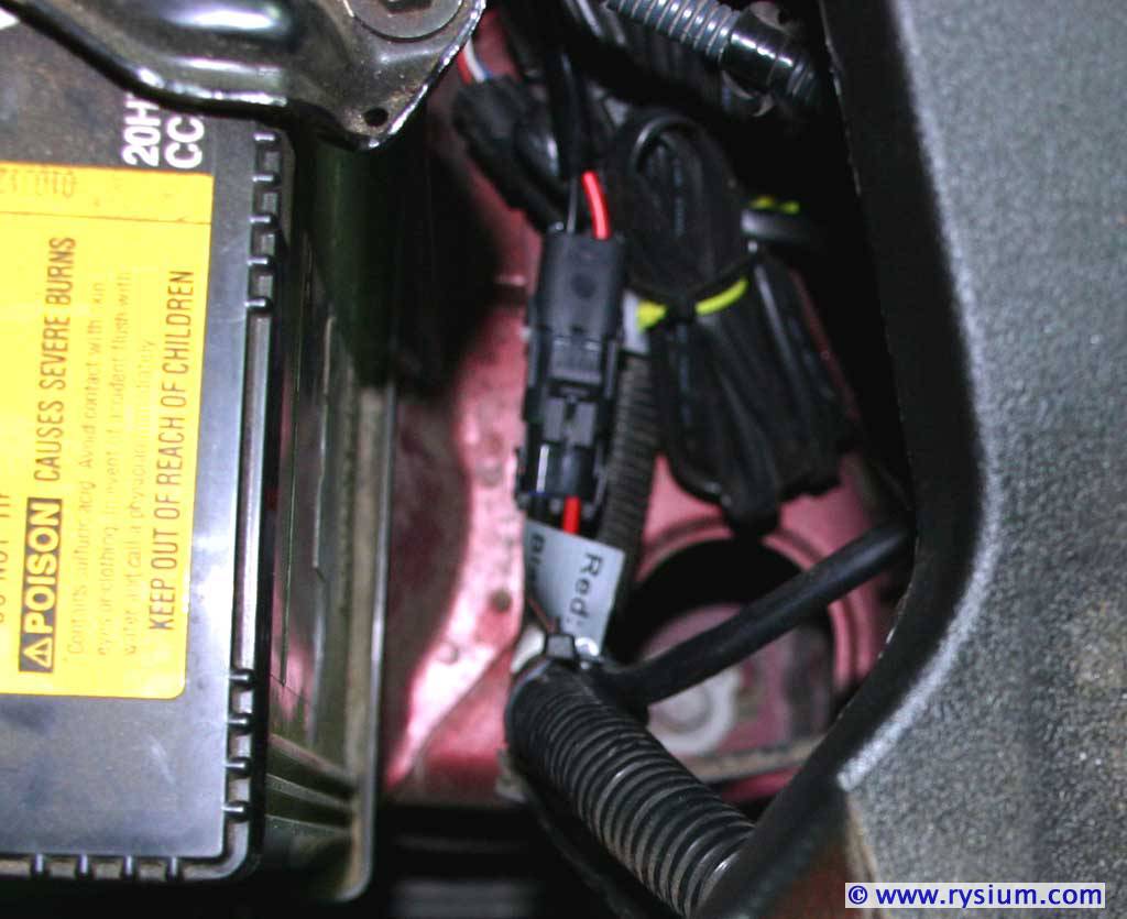
The light bar wire did not come with connectors and probably I was expected to "hardwire" it to harness. I did not like it, so I ordered Delphi Weather Pack 2 Pin Sealed Connector Kit 12-10 GA. Connectors are waterproof, similar to all connectors under the hood, and they are rated for 20A. They should be OK for 10A light bar.

4Runner-Fusebox-13.jpg


4Runner-Fusebox-14.jpg


Before ordering them on ebay ($4.19 a piece) I was looking if I can by them cheaper "online". There are few companies I could by all pieces for total about $3.50 a set but I would have to pay "standard wholesale" shipping. It may be worth when I order 20 sets. So I recommend the guy on Ebay - connectors are good quality, relatively inexpensive, and vary fast free shipping.

I did not see any "China version" of these Delphi connectors, only smaller (1.5MM 2 Pin Way Waterproof Terminals Car Electrical Wire Connector) for about 1 dollar a piece but thy are rated for only 10A (some claim 14A, but I don't believe that).

What really I don't like from makers of "kits" is that they make the wire harness "one fits all" and in result it doesn't feet any vehicle. Instead of having all connectors crimped and wires cut to "whatever size" I would rather have all elements not connected, so I can cut wires to size before crimping connectors. Otherwise the installation would look like one of shown on "easy installation steps" videos with wires going across, relays and fuses zip-tied to some other wires and length of unused wire coiled under the hood. This in not the first kit that has this problem. When I installed OSRAM LedFog kit, I had to coil excessive long wire as seen on the picture below.

So first thing I did I had to cut excessive length of some wires and replace some of wires that were to short. Then instead of having the lamp "hardwired" I installed Deplhi weather sealed connector.

4Runner-Ledbar-11.jpg


Connectors are rated for 20A and they are waterproof. They will last this car's lifetime or more.

I mounted supplied 40A relay by bolting it to the last M8 threaded hole in the fender and connected the first set of wires to my new fuse box. The white wire will go to the cabin to AOB switch.

4Runner-Ledbar-12.jpg


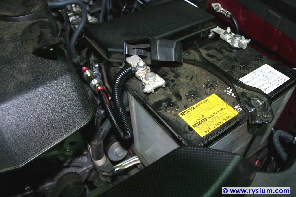
While showing pictures of the fuse box I did not show how the 80A main fuse is connected to the battery as I connected it when all circuits were ready now. So here it is:

4Runner-Ledbar-13.jpg


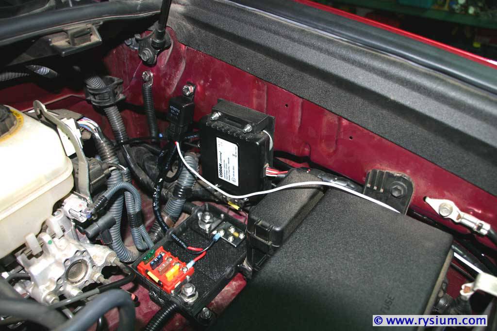
And finally the picture of all element under the hood. The fuse box is still open here and the white wire will go to the switch in the cabin (yes, it goes in the wrong direction on these pictures).

4Runner-Ledbar-14.jpg


So now all work under the hood is completed. I tested the setup by connecting the white wire to the battery plus (via 5A fuse of course) and the relay clicked and the LED bar turned on. All good.

This concludes Step 3 - Under the Hood LED Bar Wiring.

The next, last step will be installing switches in the cabin (I mean one for LED bar, and the other for rear fog lamps that are still waiting for final connections).

To be continued...
 
Last edited:
Step 4 - Switches in the cabin installation

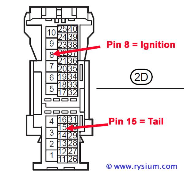
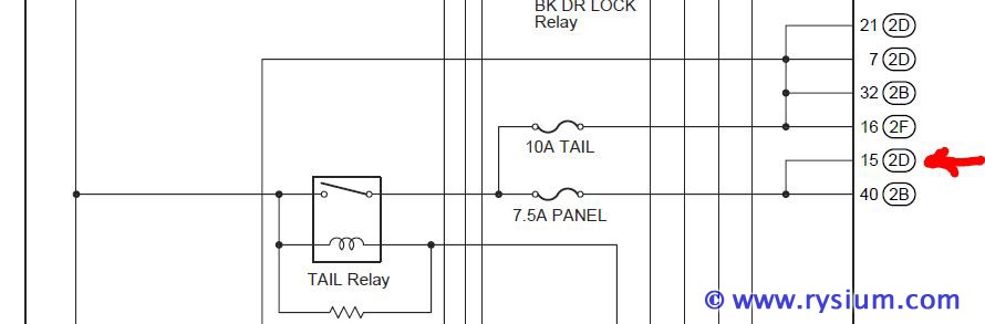
No pictures yet, as first I need to do some "legwork". How to make connections safe, easy and elegant. The big help was OSRAM LEDFOG101 light installation I did last year. Thanks to that I have already pigtail wire on 12V panel circuit (Pin 15 on connector D in Master Body ECU) that is fused by 7.5A.

4Runner-2D-15.jpg


4Runner-2D-15-fuse.jpg


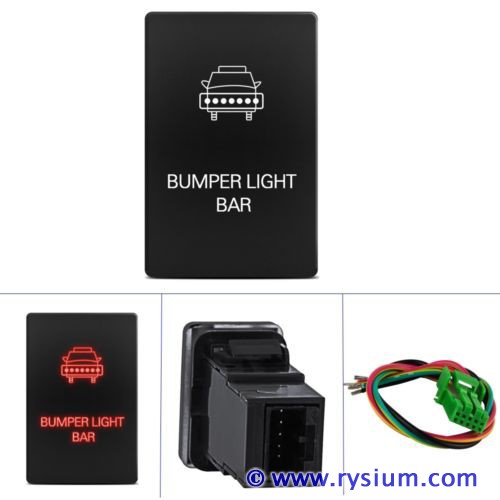
This will be my +12V to power AOB switch. Because the same 12V will be used to power relay and both LED inside the switch, I have connected Blue and Green wire internally. I have also removed the Blue wire from AOB pigtail leaving me with just Green (+12V In ), Red (12V Out) and Black (Ground).

The Light Bar switch:

4Runner-Ledbar-10.jpg


After the change the connection is very simple:

AOB Green (+12V In) connected with Tail lamp circuit (pigtail to Pin 15 on connector D in Master Body ECU

AOB Red (+12V Out) connected with white wire from the LED Light Bar relay

AOB Black (Ground) connected to illumination dimmer (I will tap to grey wire in any of dash switches near by).

I know I could power the AOB switch directly from the battery (via 3A fuse) but I don't mind to have limitation to turn the light bar only when the tail light is on. I also wanted to make sure that I will not introduce any "unexpected" signals to dimmer rheostat circuit when the tail light is off.


I modified the AOB switch by replacing bottom LED with "Toyota orange" and the top one with green. The way I'm connecting AOB switch I will be able to dim both LEDs in the switch.

Now for the actual work under the dash I will be doing more connections. I need to connect the second AOB switch that will be powering relay for rear fog lights. This is also modified switch (yes, you can tell I like to modify anything I put my hands on :eyebrows:). Only the orange LED is dimmable, the red LED is not.

4runner-fog-light-switch-mod-01.jpg


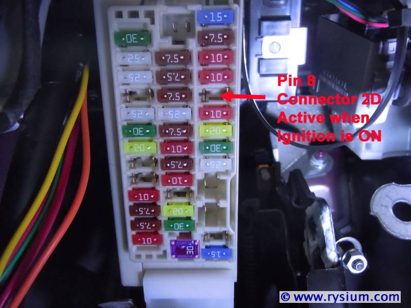
This one will have separate ground (Blue wire) and dimmer connection (black wire). Green wire will go to tail +12V and the red wire will go to relay. The legal requirement is that the rear fog light must be turned off automatically when the ignition is turned off, so the relay switch is powered from my other pigtail in Pin 8 on 2D connector on Master Body ECU. This pin is fused by 7.5A.

4Runner-2D-8.jpg


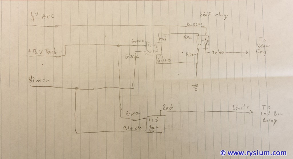
Here is the whole "behind the dash" diagram

4Runner-Ledbar-15.jpg


To be continued...
 
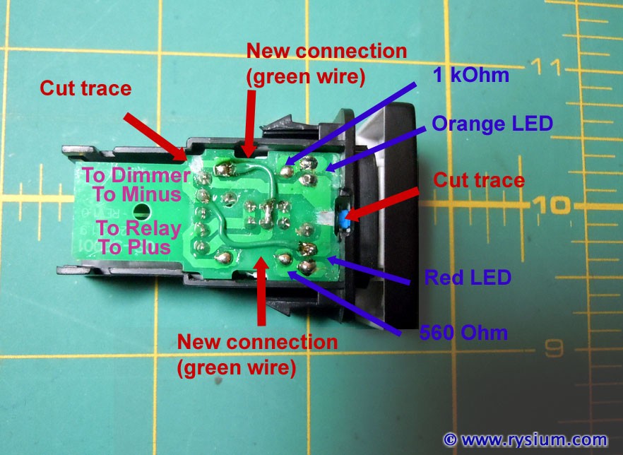
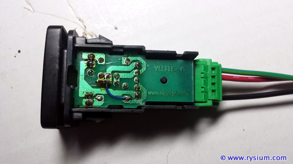
Some details about the light bar switch mod (AOB clone of ebay). First I did get rid of blue wire and connected both minuses (former blue and black wire) inside the switch. Easy job required to pop out the side cover. Picture explains everything

4runner-light-bar-switch-mod-01.jpg


Then a little bit mode soldering and opening guts of the switch were required to replace LEDs - I put "Toyota Orange" for back lit the text (when marker lights are on) and green to back lit the symbol (when led bar is on). The result is pleasing.

4runner-light-bar-switch-mod-02.jpg


To be continued...
 
I skipped all the steps for removing all panels as these steps are well described on the forum already. It is not really complicated:

1. Remove left door weather strip held only by pus-on clips
2. Remove left kick panel held only by push clips and one push pin (next to foot rest)
3. Remove left console trim panel held only by push clips
4. Remove the under the steering wheel panel held by 2 bolts and push clips (one bolt is under the flap on the right side)

Here is the bottom panel removed showing two knock-off plugs between two factory switches.

4runner-light-bar-switch-inst-01.jpg


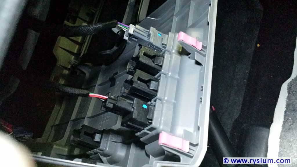
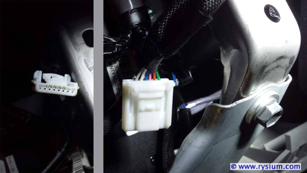
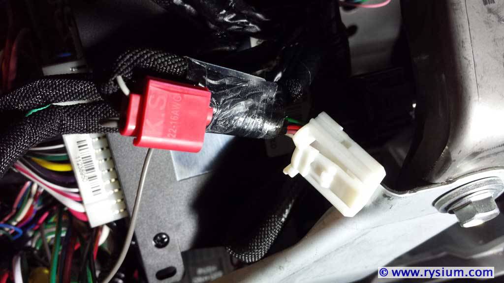
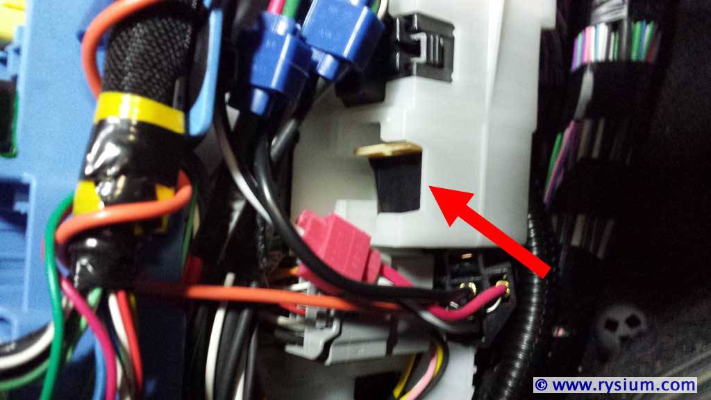
After removing the panel I noticed two unused connectors. They are just taped in but not connected to anything. It took me a while to figure out what they are for. So here is the first white 8-pin connector with 6 wires on pins 2 through 7

4runner-light-bar-switch-inst-02.jpg


I'm 99% sure this one is for running board switch. I have SR5 (not Limited) so I don't have automatic running boards, but it looks like some wiring is already there. This switch is lighted so the grey wire is for dimmer illumination, the green wire is connected to tail light +12V. I don't have electric diagram of automatic running boards so I don't know what other colors are for.

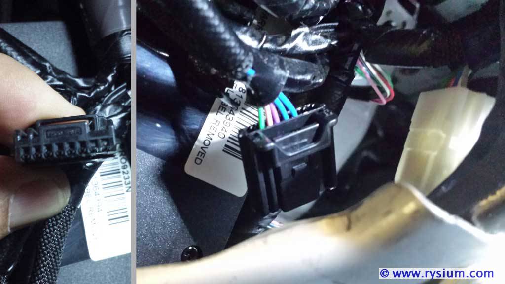
The second connector is black 8-pin connector with 5 wires on pins 2 through 6.

4runner-light-bar-switch-inst-03.jpg


This one is used for 120V Power outlet switch. Two blue wires are 12+ from ACC behind 10A fuse, remaining wires (pink, violet and green) go to Inverter Unit. In my SR5 I don't have 120V power, but again looks like some wiring is already in place.

I decided to use grey wire from running board switch to tap into dimmer circuit. This way I don't need to touch existing switches.

Now when I was installing AOB switches I hit a problem, that nobody reported. Here is the close view of the hole after knock-out plug was removed.

4runner-light-bar-switch-inst-04.jpg


Notice four notches in each corner (two are visible on this picture) that are raised above the base of mounting hole. When the switch is installed the back of the switch button is hitting these notches not allowing to engage the switch. The solution was to cut all notches flat before installing AOB switch:

4runner-light-bar-switch-inst-05.jpg


The rest was just connecting all wires. Because I was installing rear fog light switch at the same time, I had much more wires to connect (including rear fog light relay circuit). Here is the bunch of new wires packed together with zip-tie.

4runner-light-bar-switch-inst-06.jpg


I used 22-18 AWG tap connector to connect my switches to dimmer circuit. I hate this method but because I was tapping into unused wire (I will never install automatic running boards) I accepted it. Just this one time.

4runner-light-bar-switch-inst-07.jpg


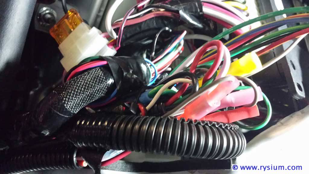
I installed rear fog light relay in the empty slot behind the kick panel. The red arrow points to the relay. There are blue wire taps and some relay put by alarm installer. Oh boy, if it doesn't break I have to live with it.

4runner-light-bar-switch-inst-08.jpg


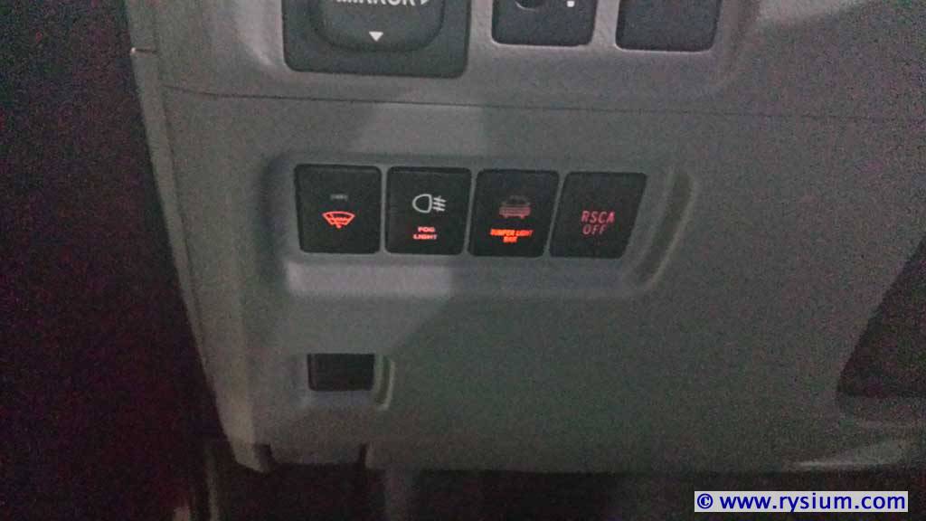
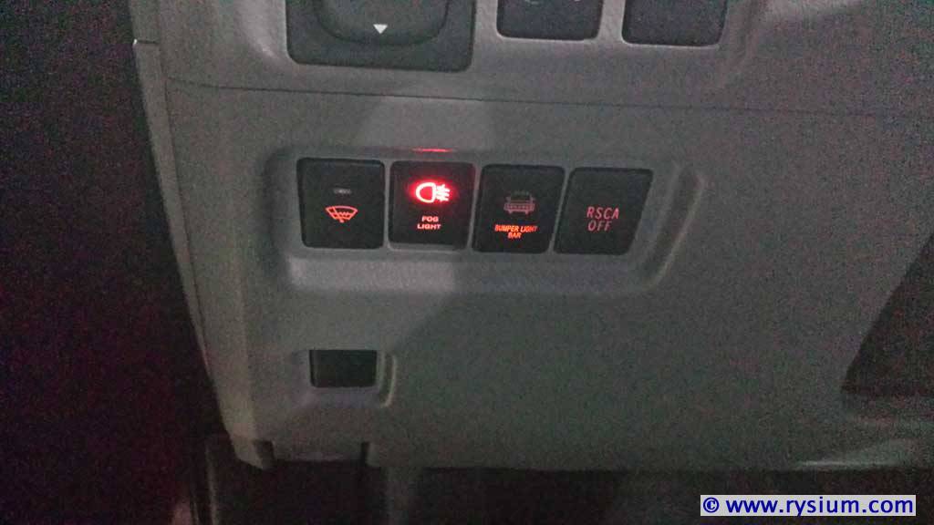
I did not relocate any other switches so after putting panel in place here is what I have:

4runner-light-bar-switch-inst-09.jpg


From the left:
- factory wiper heater switch
- new AOB rear fog light switch
- new AOB (China knock-out) led bar switch
- factory curtain airbags override switch

I was surprised that the color of the white symbol matches better factory switches in China knock-out switch. In the original AOB the white symbol is just to white.

This is how switches look when I turn tail light (night driving)

4runner-light-bar-switch-inst-10.jpg


Now I see I made a mistake. Orange lighting in my modified switches are much brighter than in factory switches. I should not have changed these resistors. Probably one day I will put original resistors back.

And finally the picture with both switches on.

4runner-light-bar-switch-inst-11.jpg


I am very pleased with the result. Maybe the red light in rear fog light switch could be a little brighter. This is important that the red light is visible as you will get a ticket in Europe if you drive with rear fog lights on when the visibility is more than 50 meters (150 ft).

I did not put pictures of the LED bar shining - it is like any other led bar - bright, white (6000K) and blinding.


This concludes Step 4 - Switches in the cabin installation

Please note, that I updated the "Fuse Box" section. I decided to connect negative wire directly to battery instead to inner fender.

THE END
 
Last edited:
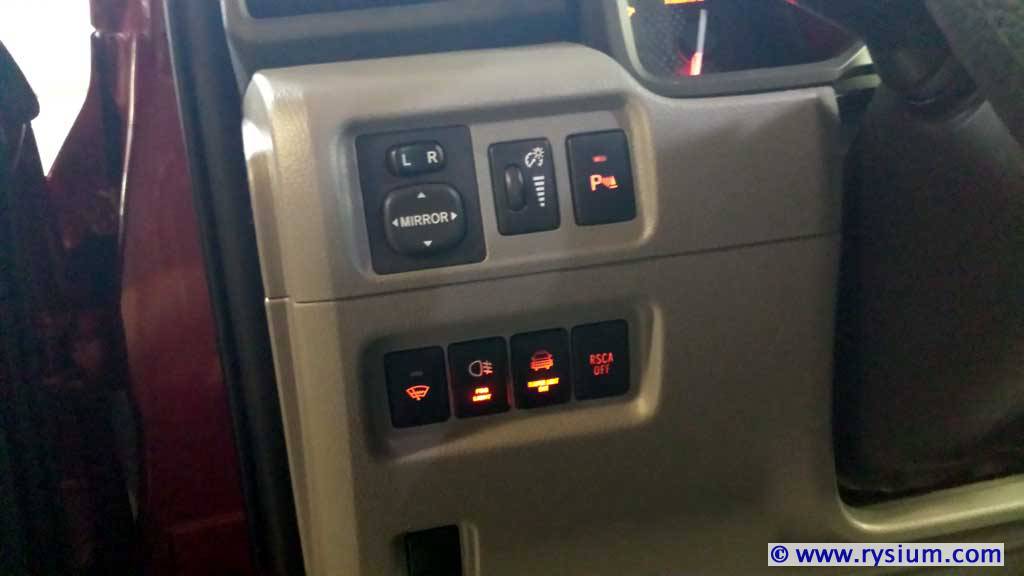
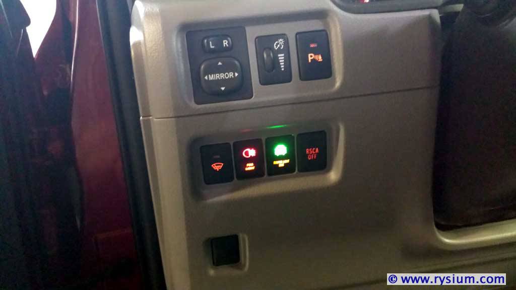
Like I wrote I did not like that AOB switches were brighter than original orange switches. I remember I replaced orange LED resistor in Fog light switch but I did not remember about LED Bar switch. So I opened again both switches.

I was surprised that LED Bar switch still had original 3kOhm resistor in orange LED, but is still brighter than should be. Multiple trials en errors brought me to installing 10kOhm resistor in place of original 3kOhm in both switches (only for orange backlight). This value made both switches very close in brightness to original Toyota switches.

Here are modified (again) switches installed.

Tail lights turned on, dimmer about half way down:

4runner-light-bar-switch-mod-03.jpg


Turning on LED Fog lights

4runner-light-bar-switch-mod-04.jpg


Turning on LED Bar light

4runner-light-bar-switch-mod-05.jpg


On the picture it looks like orange light in LED Bar switch is a bit brighter than surrounding switches, but this is actually the same brightness as factory Parking Sensor switch. I thing the camera angle or color sensitivity in low light condition makes such image. This is the image of the switches with dimmer cranked all the way up (full brightness).

4runner-light-bar-switch-mod-06.jpg


Now I am very pleased with my switches. But I see one more fix coming. I don't like the way the relay is bolted to the fender. It is not that solid as I would like as the mounting plastic in 40A relay is kind of flimsy. I am going to print some support for it.
 
I don't like the way the relay is bolted to the fender. It is not that solid as I would like as the mounting plastic in 40A relay is kind of flimsy. I am going to print some support for it.

So I did. I designed and printed a ABS plate with three zip-ties holding relay. The plate is bolted to the fender and now I am very happy with the install of my LED bar.

4runner-light-bar-relay-01.jpg


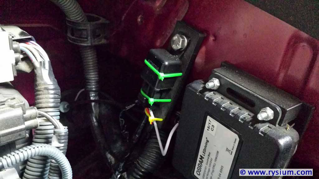
Now this image shows the white wire coming out of the relay and going into the tube together with all other DRL/FOG LED wires through the firewall. Als you can see that the 80A negative wire is not there anymore - it is connected straight to the battery.

BTW We are so lucky in Sacramento Valley that rust does not exist here. However because I will be moving the truck to Europe where the rust attacks every piece of metal, all bolts, nuts and washers I'm using are SS. I hate rust.
 
Last edited:
I did not put pictures of the LED bar shining - it is like any other led bar - bright, white (6000K) and blinding.

Nah, what the heck. Everybody does it. And BTW it looks cool :jump:

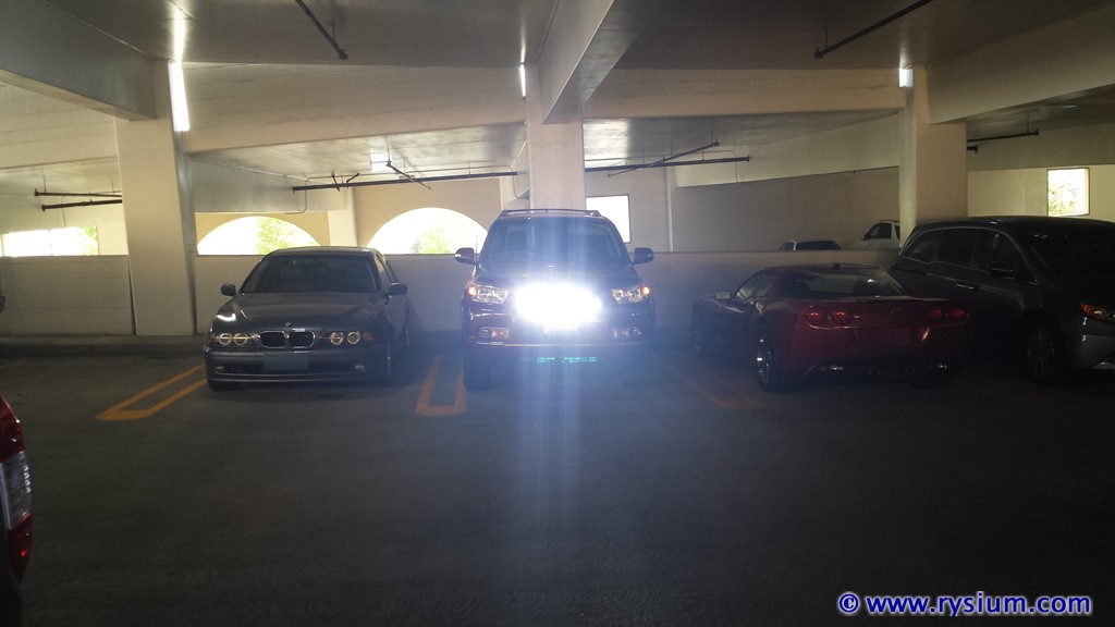
Light bar only:

4Runner-Ledbar-16.jpg


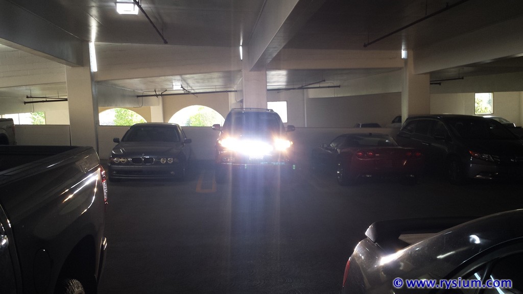
I like the way the light bar fits in line between headlights (hi + lo beam + bar)

4Runner-Ledbar-17.jpg


Yah baby :tea:
 
On my vacation road trip I found this light bar very useful when driving through Yellowstone after dark. Even with high beam (stock halogen) it is hard to see a dear waiting for you at the side of the road. Stock yellow halogen light does not expose light brown dear just waiting to jump in front of the car. On the other hand 6k white LED light makes all "wildlife" quite visible from the distance. This light bar saved my bacon in Yellowstone at least twice (I was able to see dear and slow down before passing it).

The only problem was the light bar switch position - not as convenient as stock hi-low beam stick. I think I will couple my light bar with Hi-beam. I never use hi-beam when there is a visible car in front of me (either my or opposite traffic) so adding light bar to high beam should not create a problem. This "coupling" would be on the separate switch anyway, so I will have an option to use high beam and light bar independently or together.
 

Members online

Forum statistics

Threads
278,312
Messages
3,554,089
Members
248,016
Latest member
Advally Service

Trending content

Back
Top