 12-27-2012, 02:08 PM
|
#1
|
|
Senior Member
|
|
Join Date: Sep 2011
Location: Dallas, TX
Age: 53
Posts: 1,807
|
|
|
Senior Member
Join Date: Sep 2011
Location: Dallas, TX
Age: 53
Posts: 1,807
|
"Big Three" ground wire upgrade
has anyone done the big three ground wire upgrade of their three main electrical wires to decrease the resistance in the electrical system, which purportedly improves current flow and minimizes or even eliminates voltage drops?
1. battery (+) to alternator main power wire
2. battery (-) to frame ground
3. engine block to body ground (located on the back of the motor between the firewall and the block)
does replacing the stock factory oem wiring with lower gauge heavy wiring, e.g. 1/O high strand wire, really help the engine run better and maybe even improve mpg? or would I need to simultaneously replace the factory alternator too?
|

|
 Reply With Quote Reply With Quote
|
|
12-27-2012, 03:27 PM
|
#2
|
 |
Senior Member
|
|
Join Date: Aug 2010
Location: Boston MA
Age: 40
Posts: 3,394
|
|
|
Senior Member
Join Date: Aug 2010
Location: Boston MA
Age: 40
Posts: 3,394
|
Quote:
Originally Posted by hrt4me

has anyone done the “big three” ground wire upgrade of their three main electrical wires to decrease the resistance in the electrical system, which purportedly improves current flow and minimizes or even eliminates voltage drops?
1. battery (+) to alternator main power wire
2. battery (-) to frame ground
3. engine block to body ground (located on the back of the motor between the firewall and the block)
does replacing the stock factory oem wiring with lower gauge heavy wiring, e.g. 1/O high strand wire, really help the engine run better and maybe even improve mpg? or would I need to simultaneously replace the factory alternator too?
|
This upgrade is really for if you have made significant additions to the power system, like a winch, aftermarket stereo system, compressor, etc., anything that drains alot of current. I don't think you will see alot of improvement (if noticeable at all) if you are fully stock.
__________________
2000 SR5 3.4L V6 Automatic 4x4, e-locker, 175k Miles, Rust
Imp. Jade Mica with Oak Leather Interior, Field Monitor Unit - B&M Tranny Cooler - SG2 - New (to me) rear axle assembly - Goodyear Duratrac 265/75-16 - 1.8" Ironman Front Lift, OME 906/Procomp 9000 Shocks
http://www.toyota-4runner.org/3rd-ge...ld-thread.html
|
|
|
Reply With Quote
|
|
12-27-2012, 03:49 PM
|
#3
|
|
Senior Member
|
|
Join Date: Sep 2011
Location: Dallas, TX
Age: 53
Posts: 1,807
|
|
|
Senior Member
Join Date: Sep 2011
Location: Dallas, TX
Age: 53
Posts: 1,807
|
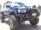
I have a new unused Warn M8000 which I intend to mount and install once I eventually find/buy an ARB front bumper...
|
|
|
Reply With Quote
|
|
12-27-2012, 04:38 PM
|
#4
|
 |
Elite Member
|
|
Join Date: Jan 2011
Location: San Diego
Age: 41
Posts: 11,437
Real Name: Instagram: briansd_97r
|
|
|
Elite Member
Join Date: Jan 2011
Location: San Diego
Age: 41
Posts: 11,437
Real Name: Instagram: briansd_97r
|
read BigFishAllDay 's thread! he did a great breakdown with pictures and part #s
----> I found "The One", 2001 Sport Ed. TRD SC'd

__________________
Those he commands move only in command, Nothing in love. Now does he feel his title, Hang loose about him, like a giants robe, Upon a dwarfish treasonous thief.
|
|
|
Reply With Quote
|
|
12-27-2012, 07:52 PM
|
#5
|
 |
Senior Member
|
|
Join Date: Jun 2012
Location: Western CO
Posts: 1,227
|
|
|
Senior Member
Join Date: Jun 2012
Location: Western CO
Posts: 1,227
|
This upgrade won't do anything for a winch, as its wired directly to the battery itself.
__________________
2000 4Runner Sport - TRD&AEM SuperCharged
Solo Long Travel & KING 2.5 & bumps, 4th gen rear axle & KING 2.5 12's
F+R ARB's, 4.88 Yukon's, 295 KM3s
|
|
|
Reply With Quote
|
|
12-27-2012, 08:22 PM
|
#6
|
|
Senior Member
|
|
Join Date: Sep 2011
Location: Dallas, TX
Age: 53
Posts: 1,807
|
|
|
Senior Member
Join Date: Sep 2011
Location: Dallas, TX
Age: 53
Posts: 1,807
|
Quote:
Originally Posted by rideexileex
This upgrade won't do anything for a winch, as its wired directly to the battery itself.
|
then is it only for audio components? inverter? dual batteries? OBA?
|
|
|
Reply With Quote
|
|
12-27-2012, 11:21 PM
|
#7
|
|
Senior Member
|
|
Join Date: Aug 2010
Location: Boston MA
Age: 40
Posts: 3,394
|
|
|
Senior Member
Join Date: Aug 2010
Location: Boston MA
Age: 40
Posts: 3,394
|
Quote:
Originally Posted by rideexileex
This upgrade won't do anything for a winch, as its wired directly to the battery itself.
|
Not true. The upgraded alternator wire and chassis ground wire will benefit the winch because it will help the alternator re-charge the battery.
Audio systems are wired directly to the battery too, as are compressors. In fact, everything is pretty much wired directly to the battery unless it plugs into the cigarette lighter.
If you are loading the electrical system, then upgrading the big 3 is a good idea.
__________________
2000 SR5 3.4L V6 Automatic 4x4, e-locker, 175k Miles, Rust
Imp. Jade Mica with Oak Leather Interior, Field Monitor Unit - B&M Tranny Cooler - SG2 - New (to me) rear axle assembly - Goodyear Duratrac 265/75-16 - 1.8" Ironman Front Lift, OME 906/Procomp 9000 Shocks
http://www.toyota-4runner.org/3rd-ge...ld-thread.html
|
|
|
Reply With Quote
|
|
12-28-2012, 11:20 AM
|
#8
|
 |
Senior Member
|
|
Join Date: Jul 2012
Location: South of Indianapolis,IN
Posts: 1,176
|
|
|
Senior Member
Join Date: Jul 2012
Location: South of Indianapolis,IN
Posts: 1,176
|
Thanks for this info. I may do this when I throw a second battery in for my winch. May upgrade the alternator as well.
__________________
E-Locker, Bilstein 5100,LX 450 Coils, Tundra Wheels Graphite, 33'' Duratracs, 1.5" wheel Spacers, Energy Suspension Sway Bar Links and bushings,Roll Bar, LED's, Sport Hood! XRC 9.5k Comp Winch Custom Mounted, 3rd Row Rumble Seat, B&M Tranny Cooler, Tundra Brakes, 4XInnovations Sliders, Uniden 520XL Pro CB, 4' Firestik.
My Build Thread!!
http://www.toyota-4runner.org/3rd-ge...8-limited.html
|
|
|
Reply With Quote
|
|
12-28-2012, 02:55 PM
|
#9
|
|
Senior Member
|
|
Join Date: Sep 2011
Location: Dallas, TX
Age: 53
Posts: 1,807
|
|
|
Senior Member
Join Date: Sep 2011
Location: Dallas, TX
Age: 53
Posts: 1,807
|
this is one of the projects I plan to tackle tomorrow
|
|
|
Reply With Quote
|
|
12-28-2012, 03:15 PM
|
#10
|
 |
Member
|
|
Join Date: Sep 2012
Location: Tempe, AZ
Age: 43
Posts: 72
|
|
|
Member
Join Date: Sep 2012
Location: Tempe, AZ
Age: 43
Posts: 72
|
Quote:
Originally Posted by rideexileex
This upgrade won't do anything for a winch, as its wired directly to the battery itself.
|
Ive got my winch grounded to the chasssis and upgraded the wire from the chassis to the -bat
__________________
My Build:

|
|
|
Reply With Quote
|
|
12-28-2012, 04:21 PM
|
#11
|
 |
Member
|
|
Join Date: Jun 2011
Location: Walnut Creek, CA
Posts: 159
|
|
|
Member
Join Date: Jun 2011
Location: Walnut Creek, CA
Posts: 159
|
grounds are almost always a probable cause for malfunctions. ive had lights and accessories on my rig since the beginning. (3 or 4 years) and am now just how grounds can cause bizar problems. ive had a ground not grounding out properly, and causing guage lights to come on when the cars off and the keys out. ive had lights kill the engine because they werent grounded out properly. ive always just hacked a self tapping crew somewhere and if it worked, id keep it that way. not a good idea. ive been relocating all my grounds straight to the frame and ive cleared up 100% of my little problems. ive got a hair over 1800 watts of lighting and dual 17" electric fans.  if you every run into elctrical problems. ALWAYS check your grounds. their usually a source of an issue
|
|
|
Reply With Quote
|
|
12-28-2012, 10:44 PM
|
#12
|
|
Elite Member
|
|
Join Date: Jan 2011
Location: San Diego
Age: 41
Posts: 11,437
Real Name: Instagram: briansd_97r
|
|
|
Elite Member
Join Date: Jan 2011
Location: San Diego
Age: 41
Posts: 11,437
Real Name: Instagram: briansd_97r
|
---> I found "The One", 2001 Sport Ed. TRD SC'd
Quote:
Originally Posted by BigFishAllDay
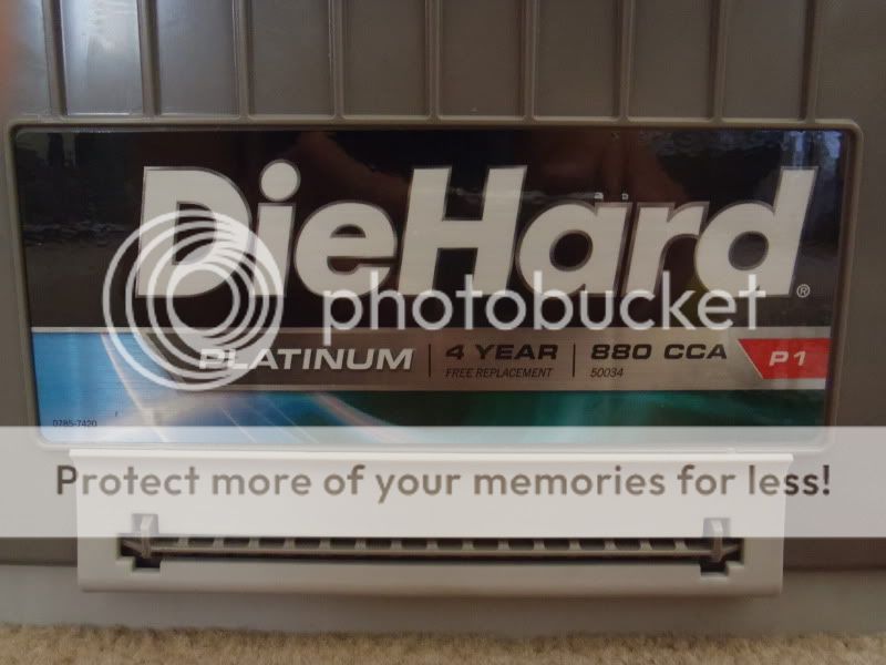
In the process of getting my winch all wired up and testing it, I found that my battery was getting weak. Once I decided on the Die Hard I started looking into other improvements to the electrical system. The only other modification that I found that yielded big results, aside from upgrading the alternator, is to upgrade the Big 3.
Im not going to type up an explanation
its been done a thousand times. The best explanation of the theory and process is at the link below, courtesy of the The12Volt.com:
How to upgrade the Big Three
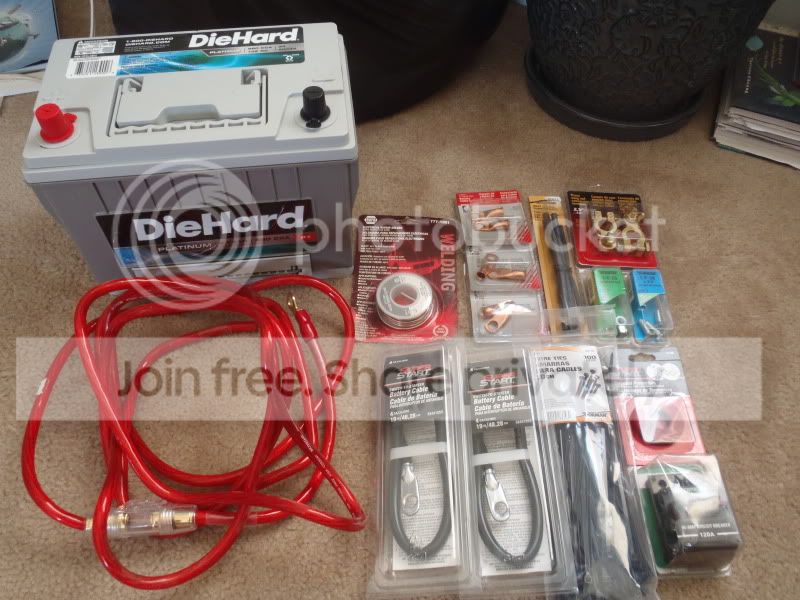
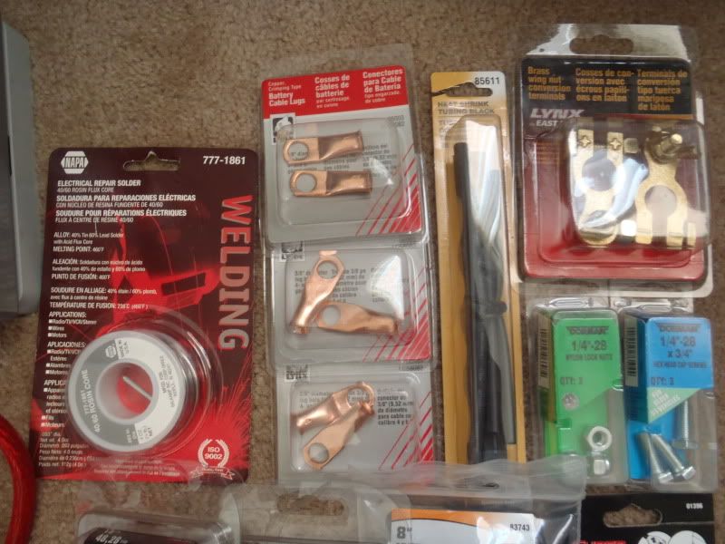
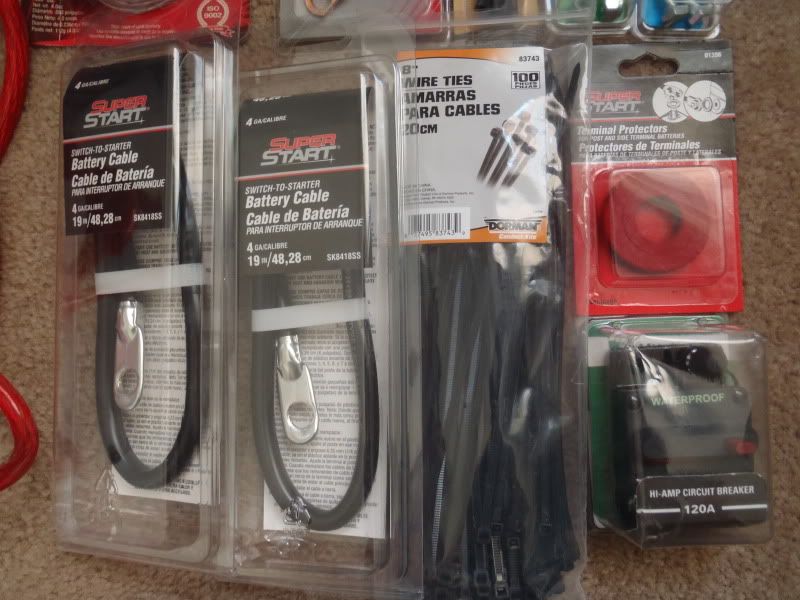
In order to install the new battery and complete the Big 3, and considering the fact that I had to extend the positive connections to install it, I needed the following:
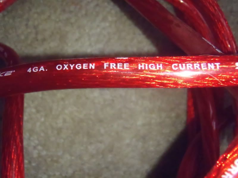
1. 8 feet of 4 gauge cable
I had some decent quality amp wiring in the garage already.
2. Some heavy gauge flux core Solder.
3. 1/2 Heat Shrink Tubing
4. Some Zip Ties
8 size is good.
5. Some new battery terminals. The jury is still out on this one, but I got some new marine terminals. Ill post more on what I end up doing with the terminals when this is all done.
6. Two 4 Gauge Battery Cables (19 inch length). Ill probably only need one, but these are for extending the positive side of things.
7. Some 1/4-20 3/4 bolts and lock nuts
8. 120 Amp Circuit Breaker (Littelfuse and Bussman both make a good offering for around $30)
9. Felt Terminal Protectors
10. Electrical Tape.
11. 8 Copper ring terminals, 4 AWG size, 3/8 hole.
All of this additional stuff cost about $75.00.
The Goods:
I didnt get too far tonight, but I got the wires built for the Big 3 upgrade:
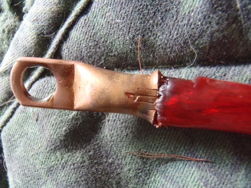
Step 1: Strip the shielding

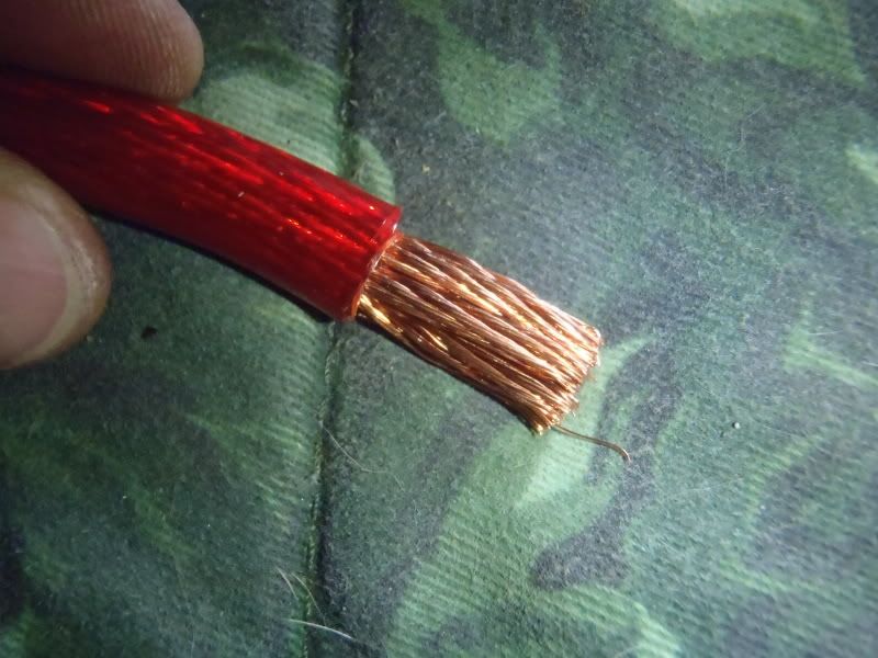
Step 2: Find a C-Clamp, place your ring terminal in the clamp, with the hole for the wire facing up
Cut a couple short pieces (1/2) of the heavy gauge solder:
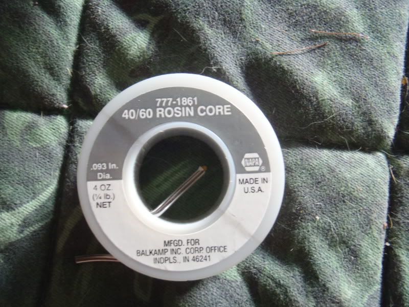
put the solder in the terminal, and heat with a propane torch until the solder melts.
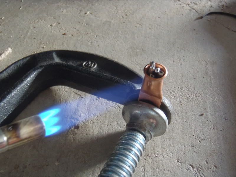
Once the solder is melted, push the stripped end of the wire into the terminal
.
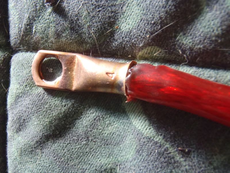
Crimp it
Vice grips worked great for me
And put some heat shrink tubing over the joint where the wires shielding meets the terminal.
All built
.
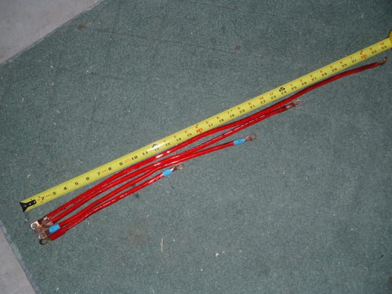
To be continued tomorrow. Hopefully Ill be able to get it finished up. |
__________________
Those he commands move only in command, Nothing in love. Now does he feel his title, Hang loose about him, like a giants robe, Upon a dwarfish treasonous thief.
|
|
|
Reply With Quote
|
|
12-28-2012, 10:45 PM
|
#13
|
|
Elite Member
|
|
Join Date: Jan 2011
Location: San Diego
Age: 41
Posts: 11,437
Real Name: Instagram: briansd_97r
|
|
|
Elite Member
Join Date: Jan 2011
Location: San Diego
Age: 41
Posts: 11,437
Real Name: Instagram: briansd_97r
|
And part 2 ....
Quote:
Originally Posted by BigFishAllDay
I spent a few afternoons last week finishing up the Big 3 upgrade and getting the battery installed. Everything went pretty smoothly.
After I got the wires cut to length, and terminals soldered on and crimped, I took the time to add some extra insulation and protection against abrasion. Shorts on these wires = fires, and I dont like fires in my engine bay.
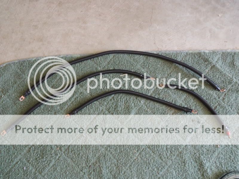
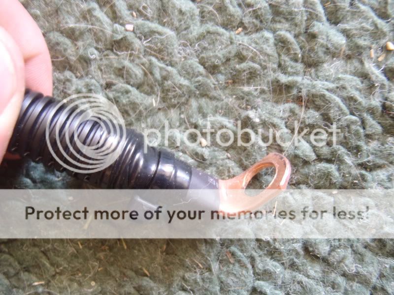
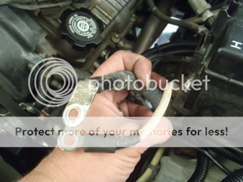
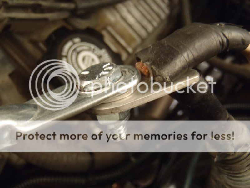
This is a close up of the engine side of the new engine to chassis ground. I had to bend the end of the terminal to accommodate the mounting location on the alternator bracket. You can also see the insulation
heat shrink tubing from wire to terminal, wiring loom over that, electrical tape over that, and then a zip tie around the electrical tape to prevent it from un-wrapping due to the heat in the engine bay.
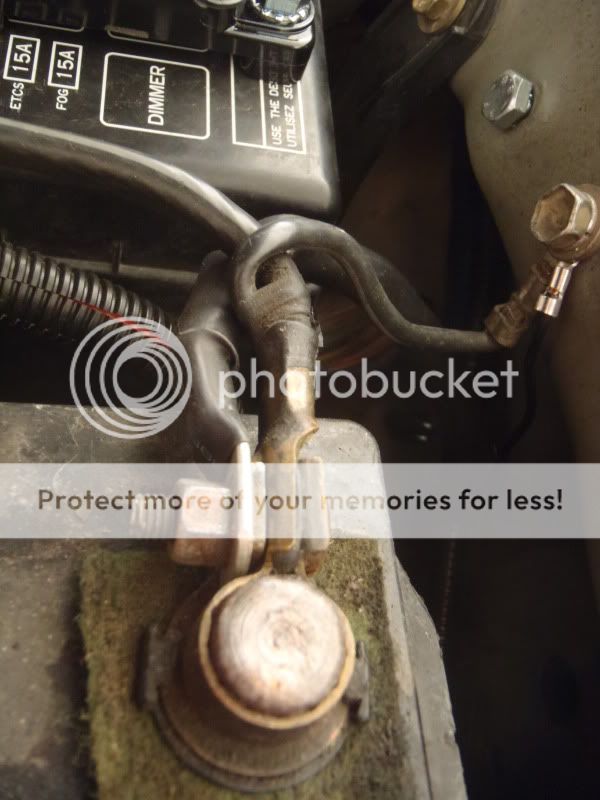
Time to get down to business, but beforehand I took a few shots of the existing setup
WEAK, weak, WEAK battery to chassis ground
this is probably the weakest link of the stock wiring.
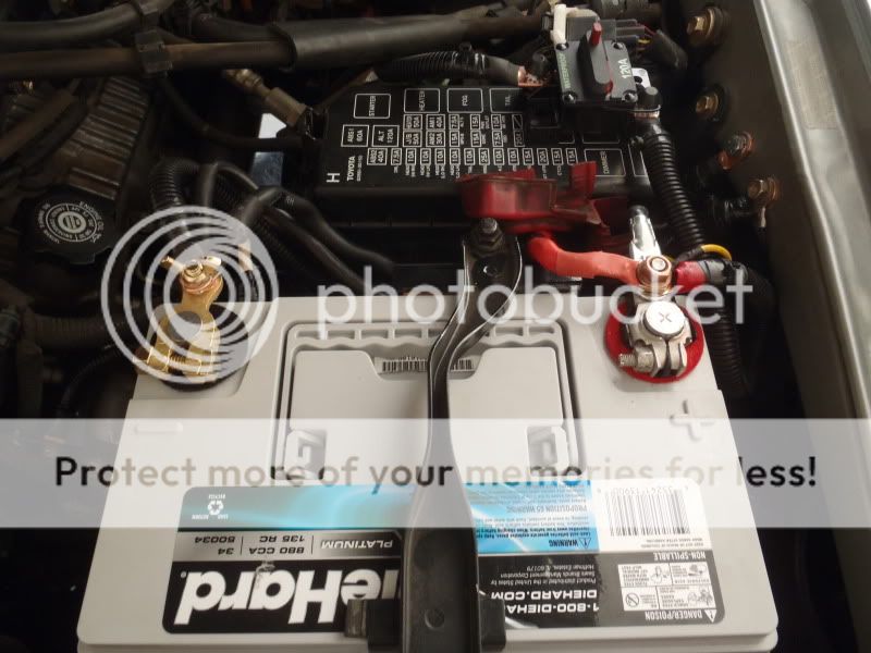
Positive terminal
Wires attached are Alternator charge wire > Batt
Alt > Fuse Box > Fusible Link > Batt
. Winch Positive Terminal > Batt
.. and IPF Lighting Positive > Batt.
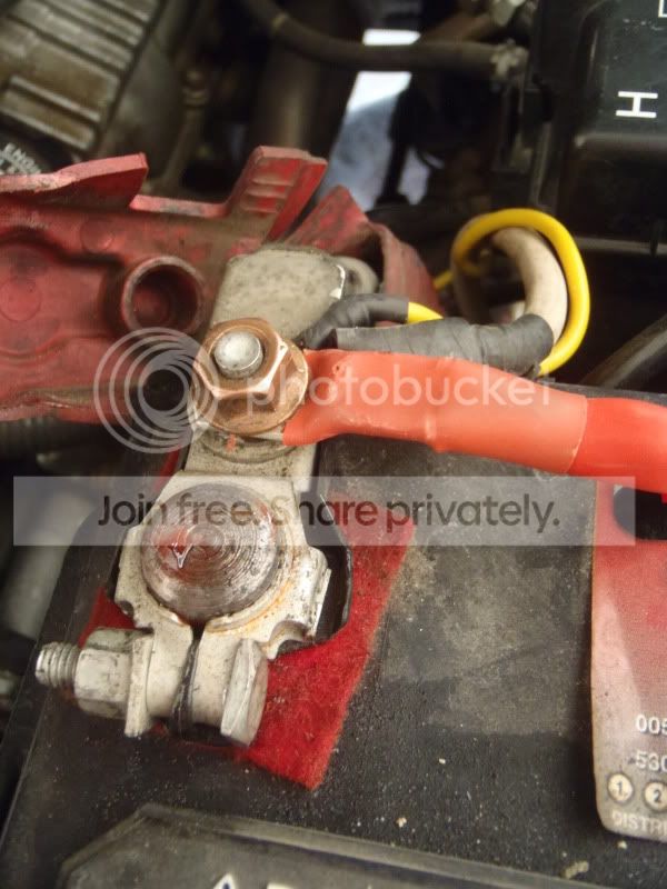
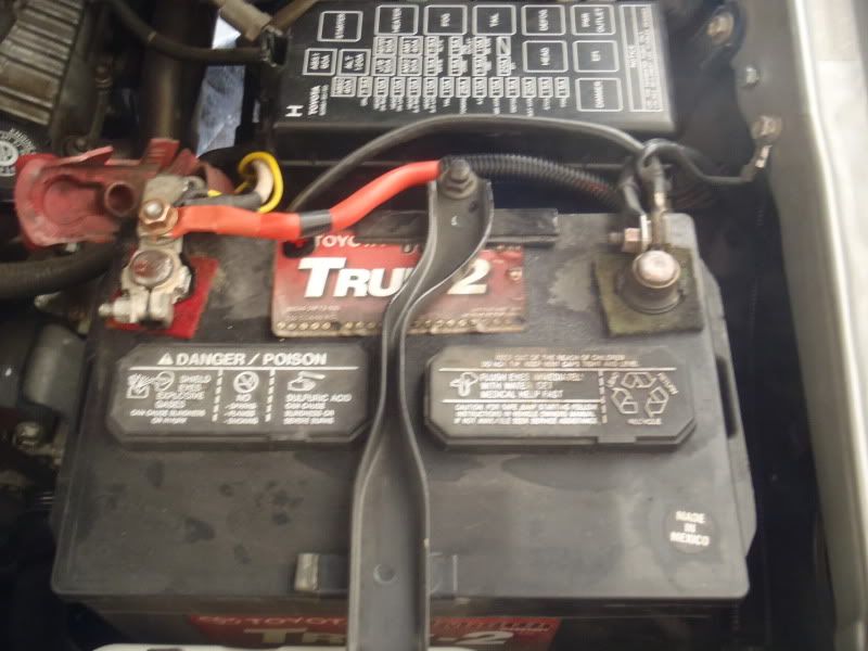
The whole shebang
. A leaky battery = one of my engine bay pet peeves!
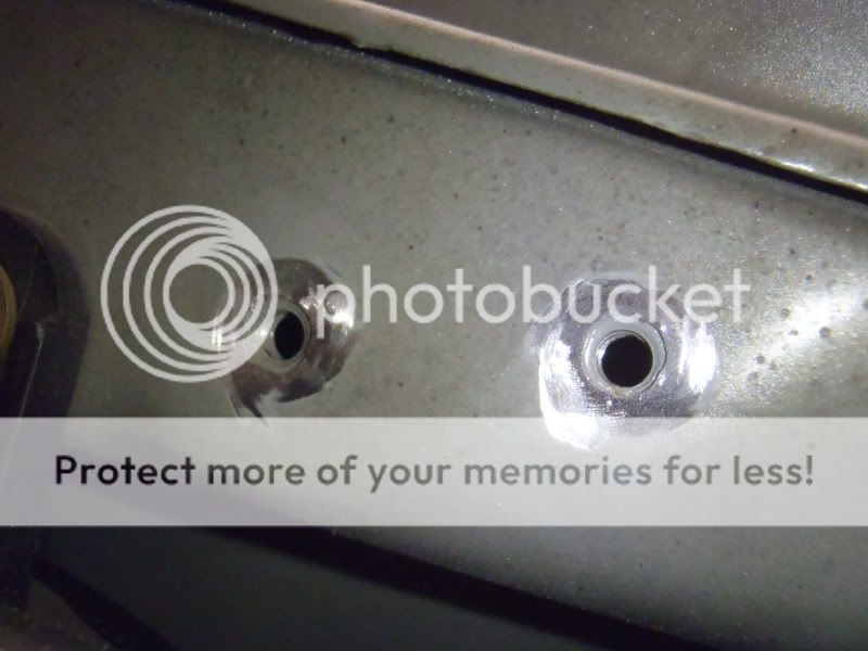
I took the paint off the inner fender @ the ground locations for a better ground connection. I ended up using the stock ground location, and another unused bolt hole located about 2 inches rearward.
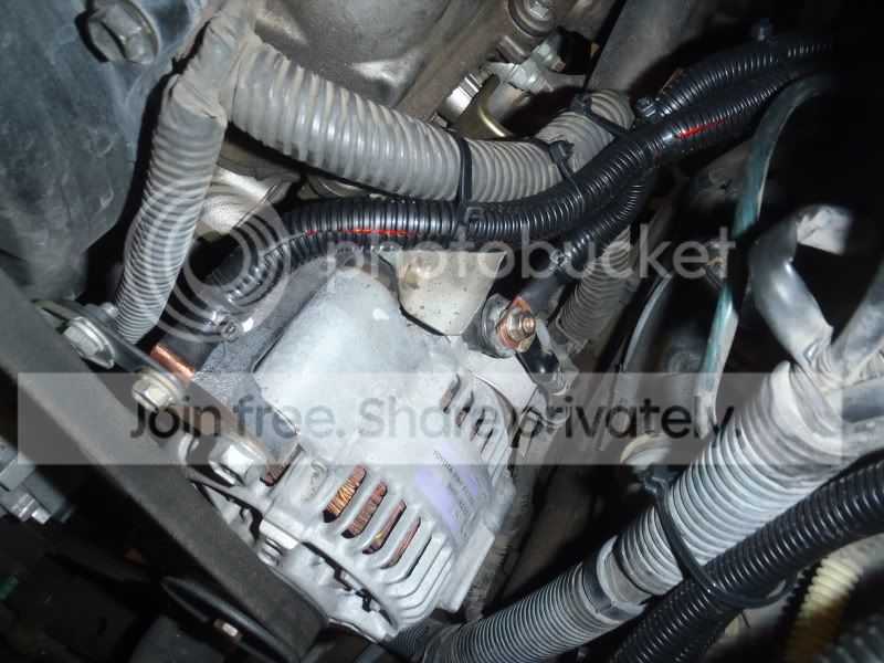
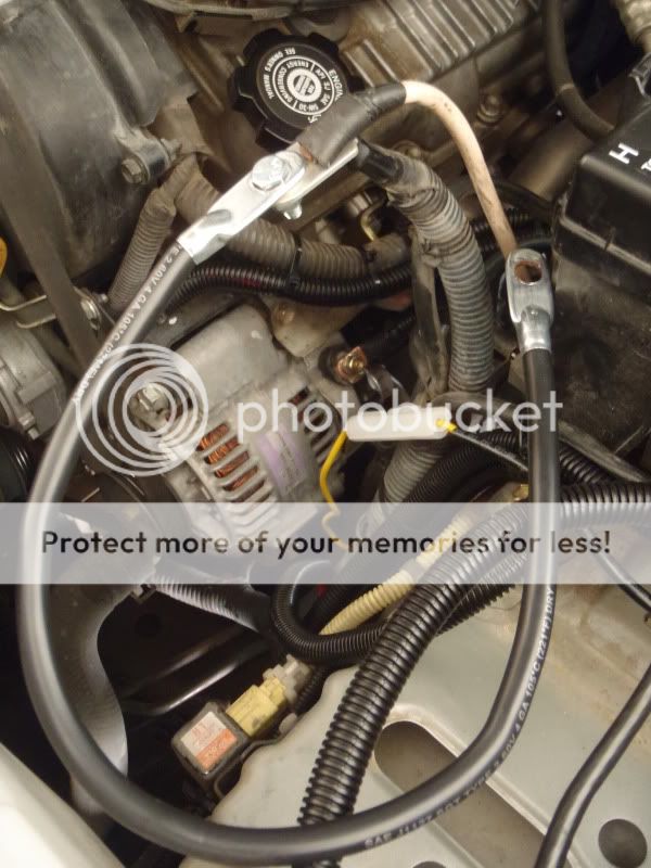
I then hooked up 2 of the Big 3 wires at the alternator side. The Engine to Chassis ground can be connected anywhere on the engine block to anywhere on the chassis. Since the alternator case is the ultimate grounding point of the entire electrical system, I decided to hook up right to the mounting bracket where I would be electrically closest to the alternator case.
The second connection was at the (+) Charging Post on the alternator. You can see the connection to the alternator mounting bracket at left (notice the bent terminal, which I had to do to keep the wiring out of the path of the alternator drive belt), and the connection to the alternator charging post at center
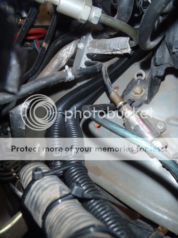
The new wires follow the existing wiring rearward, then separate off toward the drivers side behind the fuse box
.
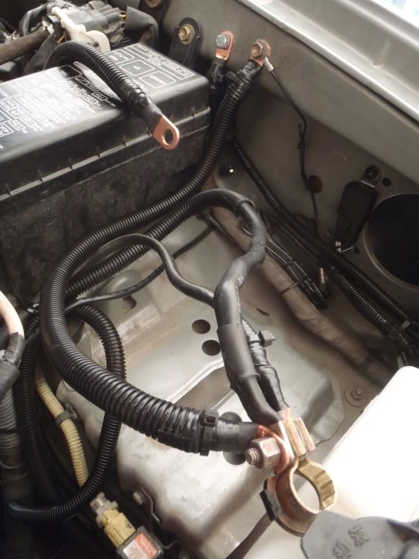
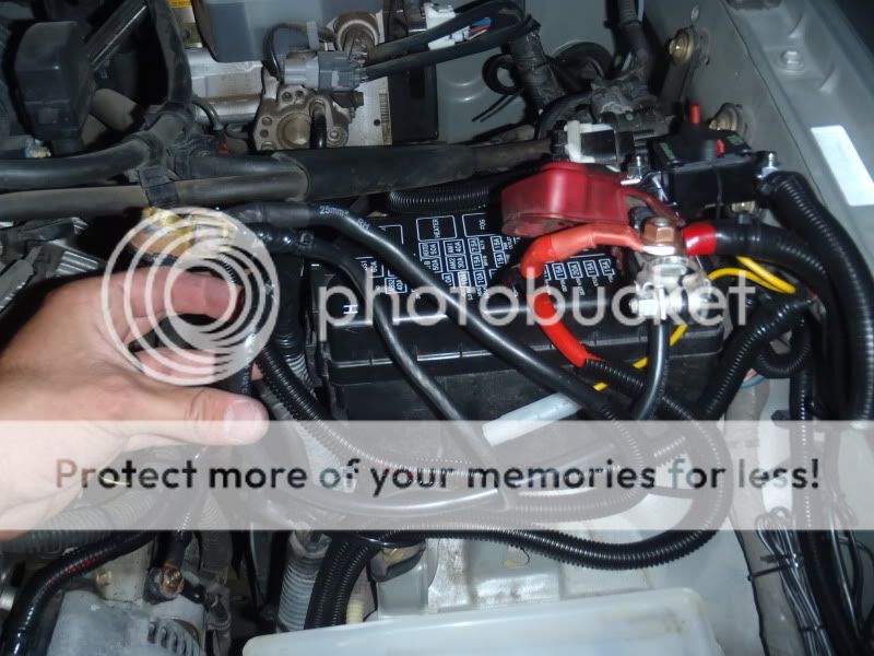
The third wire of the big 3 is the Battery (-) to Chassis wire
I connected one side to the negative terminal and the other side to the stock grounding point on the inner fender. In this shot you can see the Battery (-) to chassis wire in the foreground, the Alternator Case (Engine) to Chassis wire connected to the inner fender just behind it, and the new Alternator Charging Post to Batt (+) wire draped over the fuse box.
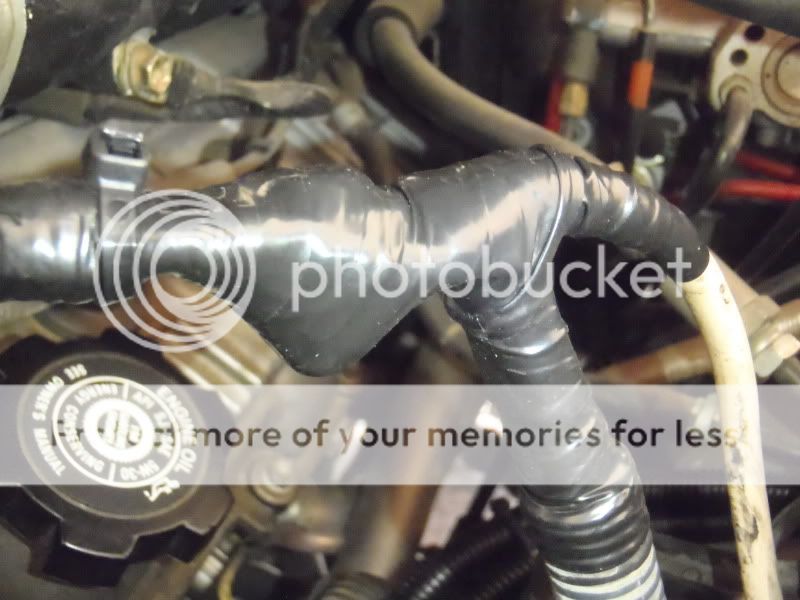
Now to deal with extending the stock wiring on the (+) side of things. The two wires that need to be extended are the stock Alternator to Batt (+) wire, and the fusible link coming from the fuse box. The simplest way to do this is like so:
The extension wire is 19 inches long, 4gauge and should have plenty of current carrying capacity to serve as a jumper from the existing wires to the Battery (+) terminal. The bolt and lock nut make sure that there is a strong connection that wont come loose over time. Finally, I made sure to insulate the hell out of it. I took the entire junction and wrapped it in high quality electrical tape, wrapped that in thick plastic sheet, wrapped with more electrical tape, and repeated one more time. Adding the plastic sheet makes sure the bolt wont eventually wear through the electrical tape and ground out
again, NO FIRES!
I then had enough length on all the (+) cables to make the connection to the terminal and prepare to drop in the battery.
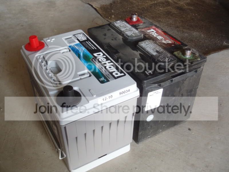
New VS. Old
Again, with the spacer, you can see that the group 34 battery is nearly identical in size to the group 24
.(Also, note the reversed terminals)
I ended up hacking off the old (-) battery terminal, soldering on a new copper ring terminal, and using a completely new brass battery terminal on the negative side. I felt it was much cleaner, stronger, and provided a better connection than the stock (-) terminal, which is very flimsy.
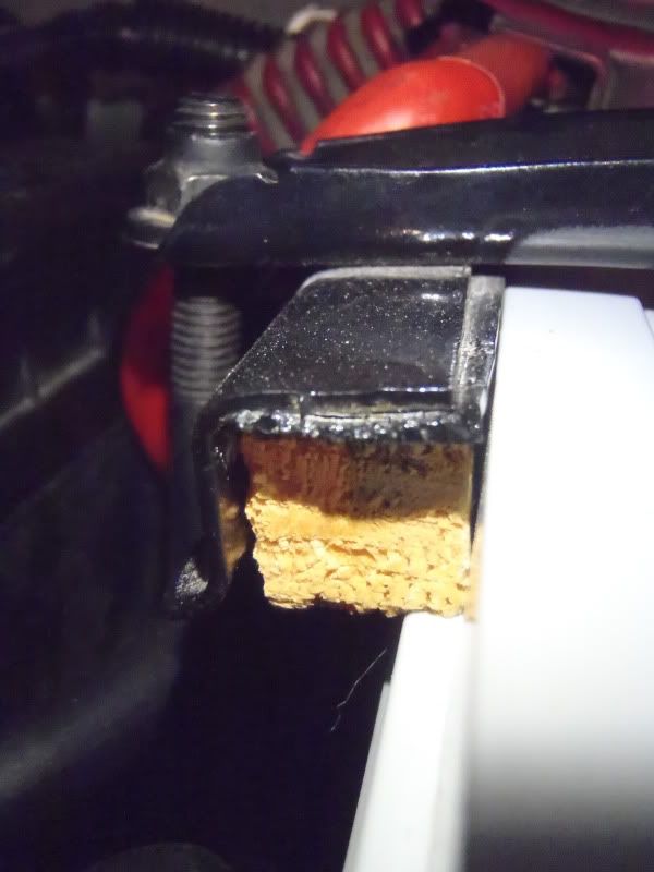
The only thing you have to do to get the stock battery hold down to work on the Die Hard group 34 is cut a small piece of wood, about 3 inches long, by 5/8 square to fill a small gap that is created between the tie down and the rear side of the battery.
Finally, the overall shot of the finished product. You can also see the new 120A circuit breaker I added inline on the new Alternator Charging Post to Battery (+) wire. I used Velcro tape to mount the breaker to the top of the fuse box cover, where it can be easily accessed in case it trips, or for troubleshooting.
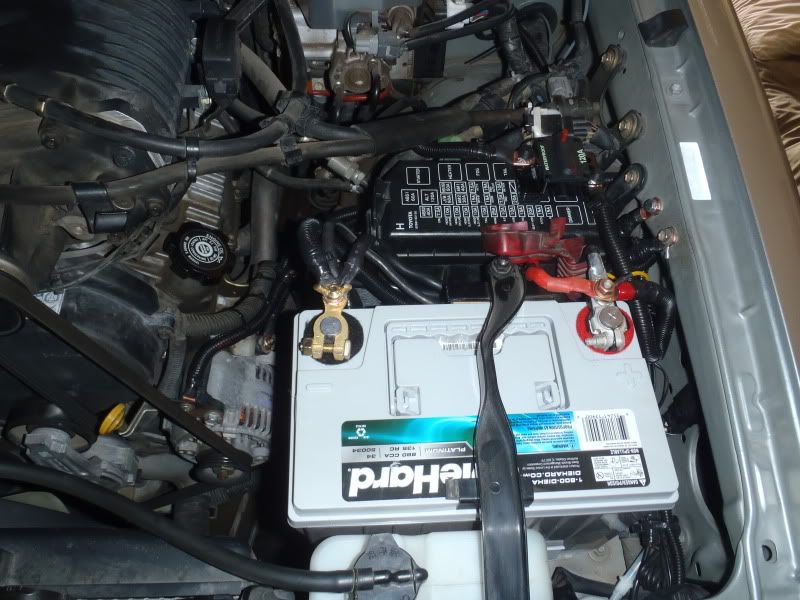 Overall, it was a pretty clean install using the group 34. I have noticed a dramatic increase in idle voltage, which came up from 11.8V to 13.3V. It seems to have smoothed out the idle a little bit, and has definitely been noticeable at night, where the lighting remains at a constant brightness. Before the upgrade, my lighting would dim SIGNIFICANTLY at stoplights or when the truck was idling. I tested the winch on the upgraded electrical system, and it is MUCH HAPPIER. On the old setup, when I activated the winch, the dash lights would flicker a bit and the alternator warning light (red battery symbol) would come on. The Scangauge showed the voltage dropping to almost 11V when the winch was on with the old setup, and with the new setup it does not go below 12.5V. Also, the truck starts much easier with all those cranking amps. For $300, I am VERY happy with this upgrade.
 |
__________________
Those he commands move only in command, Nothing in love. Now does he feel his title, Hang loose about him, like a giants robe, Upon a dwarfish treasonous thief.
Last edited by BrianSD_42; 12-28-2012 at 10:48 PM.
|
|
|
Reply With Quote
|
|
12-29-2012, 02:44 AM
|
#14
|
|
Senior Member
|
|
Join Date: Jun 2012
Location: Western CO
Posts: 1,227
|
|
|
Senior Member
Join Date: Jun 2012
Location: Western CO
Posts: 1,227
|
Quote:
Originally Posted by Nelsonmd
Not true. The upgraded alternator wire and chassis ground wire will benefit the winch because it will help the alternator re-charge the battery.
Audio systems are wired directly to the battery too, as are compressors. In fact, everything is pretty much wired directly to the battery unless it plugs into the cigarette lighter.
If you are loading the electrical system, then upgrading the big 3 is a good idea.
|
Winches have their ground return directly to the battery, and with the high current draw of the winch, it far exceeds the current capacity of the alternator, and any recharge rate. When it comes to winching, the battery is key.
The difference you were talking about is that audio systems typically use a chassis ground, where the big three would then benefit more significantly.
__________________
2000 4Runner Sport - TRD&AEM SuperCharged
Solo Long Travel & KING 2.5 & bumps, 4th gen rear axle & KING 2.5 12's
F+R ARB's, 4.88 Yukon's, 295 KM3s
|
|
|
Reply With Quote
|
|
12-29-2012, 10:56 AM
|
#15
|
 |
Junior Member
|
|
Join Date: Sep 2010
Location: Pennsylvania
Age: 41
Posts: 2
|
|
|
Junior Member
Join Date: Sep 2010
Location: Pennsylvania
Age: 41
Posts: 2
|
I run a 250A one wire cs144 alt with the big 3 done in 1/0. All I can say is it can do nothing but help all electrical components in your rig.
|
|
|
Reply With Quote
|
 Posting Rules
|
You may not post new threads
You may not post replies
You may not post attachments
You may not edit your posts
HTML code is On
|
|
|
|


 Linear Mode


