 01-15-2015, 11:36 AM
|
#1
|
 |
Member
|
|
Join Date: Aug 2010
Location: Lake City, FL
Posts: 255
|
|
|
Member
Join Date: Aug 2010
Location: Lake City, FL
Posts: 255
|
E- Locker Wiring Diagram Clarification
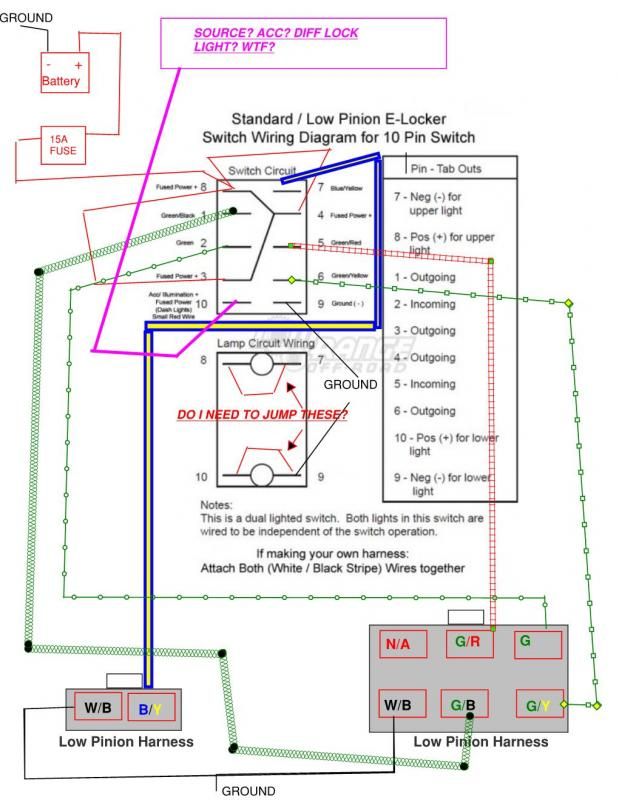
I have searched the interweb and have found nothing. I recently purchased a lowrange offroad e-locker switch for my e-locker retrofit. (Might as well turn it on right?) My intent is to install a stand alon harness as I do not want the factory ECU to be involved here, I have looked everywhere and cannot find a diagram, so I drew one. I have three questions.
1. Where should the number 10 power come from? the key switch?
2. Does the switch make the jump internally 8-7 and 10-9 or do I need to put in physical wire jumpers to make this connection work?
3. I just don't ****ing get the 2 prong harness on the bottom left. It appears to me the positive Blue/Yellow is wiring to the positive. Or am I completing the positive loop to the motor?
I will draw a 100% complete diagram when I am complete for all to share. This will be the first ever 100% complete battery to locker harness diagram.
Link to Lowrange Offroad for switch. Toyota Electric E Locker Switches check out the fifth picture for the diagram.
Many Thanks friends. Ill be bugging you about my front ARB locker next.
__________________
97 Limited 4x4 218,000 3.4 V6 4.88's E-Locker, Arb Locker 295/70r17 Nitto Trail Grapplers, Custom rear bumper, 06 Sequioa Wheels, Toytec Ultimate 3.5 Lift OME 891's Bilstein 5150's 4crawler 1.5" body lift, Spider Trac 1.25 spacers,ODL bumper, PIAA 520 and 510 SMR's, Taco Whip Mod,Pioneer Head Unit, Satoshsi grille
My Build Thread
|

|
 Reply With Quote Reply With Quote
|
|
01-15-2015, 09:57 PM
|
#2
|
 |
Senior Member
|
|
Join Date: Dec 2013
Location: Covina, CA
Posts: 2,301
|
|
|
Senior Member
Join Date: Dec 2013
Location: Covina, CA
Posts: 2,301
|
Quote:
Originally Posted by runnyrunnerton

I have searched the interweb and have found nothing. I recently purchased a lowrange offroad e-locker switch for my e-locker retrofit. (Might as well turn it on right?) My intent is to install a stand alon harness as I do not want the factory ECU to be involved here, I have looked everywhere and cannot find a diagram, so I drew one. I have three questions.
1. Where should the number 10 power come from? the key switch?
2. Does the switch make the jump internally 8-7 and 10-9 or do I need to put in physical wire jumpers to make this connection work?
3. I just don't ****ing get the 2 prong harness on the bottom left. It appears to me the positive Blue/Yellow is wiring to the positive. Or am I completing the positive loop to the motor?
I will draw a 100% complete diagram when I am complete for all to share. This will be the first ever 100% complete battery to locker harness diagram.
Link to Lowrange Offroad for switch. Toyota Electric E Locker Switches check out the fifth picture for the diagram.
Many Thanks friends. Ill be bugging you about my front ARB locker next. |
OK, near as I can tell, it looks clumsy, this is not the ideal switch for this operation. However, it will probably work.
1. The lights work independent of switch position, so #10 would need to be power from a light circuit, so when your lights are on, the lower light in the switch is on(so you can find the switch in the dark).
2. 8,7 and 9,10 are connected to either side of the two lights in the switch, they are intended to operate independent of each other, DO NOT JUMPER THEM.
3. This one is trickier, not knowing where the harness goes. But, it looks like the Blue and Yellow wire coming from term 7 on the switch is grounded by the white and Black wire, when the locker is engaged. Thus lighting the UPPER light in the switch, only when you turn it on.
OK?

__________________
1989 FJ62 5.3 Chevy, FZJ80 Axles, 4.88's with ARB.
2000 2wd runner, 4 cylinders, yes it IS slow.
1999 4WD SR5 Desert Dune 3.4 351K and counting.
2000 4WD sport 3.4 Elocker <--My son's but I still end up paying.
2001 2WD SR5 3.4 <-- My daughter's...see preceding line.
|
|
|
Reply With Quote
|
|
01-22-2015, 06:18 PM
|
#3
|
|
Member
|
|
Join Date: Aug 2010
Location: Lake City, FL
Posts: 255
|
|
|
Member
Join Date: Aug 2010
Location: Lake City, FL
Posts: 255
|
Clumsy is my middle name. Going to try this again tonight and see what happens. I had some broken connections and have since learned to solder, never again. I have the locker wired up and am connecting the switch again this evening. For test purposes I was thinking it would be smart to jack up the rear axle and roll the tires manually while testing the operation. Thoughts?
__________________
97 Limited 4x4 218,000 3.4 V6 4.88's E-Locker, Arb Locker 295/70r17 Nitto Trail Grapplers, Custom rear bumper, 06 Sequioa Wheels, Toytec Ultimate 3.5 Lift OME 891's Bilstein 5150's 4crawler 1.5" body lift, Spider Trac 1.25 spacers,ODL bumper, PIAA 520 and 510 SMR's, Taco Whip Mod,Pioneer Head Unit, Satoshsi grille
My Build Thread
|
|
|
Reply With Quote
|
|
01-23-2015, 02:12 PM
|
#4
|
|
Member
|
|
Join Date: Aug 2010
Location: Lake City, FL
Posts: 255
|
|
|
Member
Join Date: Aug 2010
Location: Lake City, FL
Posts: 255
|
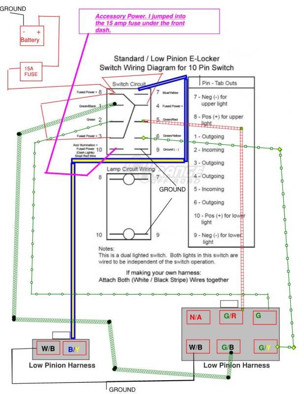
It works. Here is the accurate wiring diagram for an E-Locker for anyone interested in making their own harness. The correct switch function will go as follows.
Bottom light will light up with key in ignition.
Top toggle engages the locker and light comes on and stays on when locker engaged.
Bottom toggle disengages locker.
I know it may be basic wiring to you, but I felt like I just built an Apache helicopter.
I wold up finding a speaker wire with 7w x 16 gauge colored wires in it. Hind sight, I would buy a trailer light 4x armored 4 wire chord and run my grounds independently. Would've Been simpler. Ill post my switch mounts when complete on my build thread.
__________________
97 Limited 4x4 218,000 3.4 V6 4.88's E-Locker, Arb Locker 295/70r17 Nitto Trail Grapplers, Custom rear bumper, 06 Sequioa Wheels, Toytec Ultimate 3.5 Lift OME 891's Bilstein 5150's 4crawler 1.5" body lift, Spider Trac 1.25 spacers,ODL bumper, PIAA 520 and 510 SMR's, Taco Whip Mod,Pioneer Head Unit, Satoshsi grille
My Build Thread
|
|
|
Reply With Quote
|
|
01-23-2015, 10:16 PM
|
#5
|
|
Senior Member
|
|
Join Date: Dec 2013
Location: Covina, CA
Posts: 2,301
|
|
|
Senior Member
Join Date: Dec 2013
Location: Covina, CA
Posts: 2,301
|
Quote:
Originally Posted by runnyrunnerton
It works. Here is the accurate wiring diagram for an E-Locker for anyone interested in making their own harness. The correct switch function will go as follows.
Bottom light will light up with key in ignition.
Top toggle engages the locker and light comes on and stays on when locker engaged.
Bottom toggle disengages locker.
I know it may be basic wiring to you, but I felt like I just built an Apache helicopter.
I wold up finding a speaker wire with 7w x 16 gauge colored wires in it. Hind sight, I would buy a trailer light 4x armored 4 wire chord and run my grounds independently. Would've Been simpler. Ill post my switch mounts when complete on my build thread.
]
|
I cringe at the idea of using speaker wire for anything other than, well, speakers. 16g is cool though, just can't handle speaker wire concept.
Now the job you just did is not too complicated, but I understand where you are coming from. Hopefully you learned a little, and the next project won't be so intimidating. You can always ask for help!

__________________
1989 FJ62 5.3 Chevy, FZJ80 Axles, 4.88's with ARB.
2000 2wd runner, 4 cylinders, yes it IS slow.
1999 4WD SR5 Desert Dune 3.4 351K and counting.
2000 4WD sport 3.4 Elocker <--My son's but I still end up paying.
2001 2WD SR5 3.4 <-- My daughter's...see preceding line.
|
|
|
Reply With Quote
|
 Posting Rules
|
You may not post new threads
You may not post replies
You may not post attachments
You may not edit your posts
HTML code is On
|
|
|
|


 Linear Mode


