Quote:
Originally Posted by domstriker

Sorry, I'm not an electrician. I don't know what "switching negative" means.
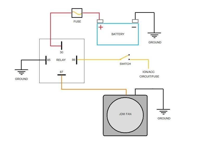
The reason I didn't go with something like diagram #5 is I don't know where to hook up to ACC power.
|
You have the switch on the ground leg (or negative side) of the coil. In #5, the switch takes positive from the ACC circuit and the other side of the coil goes direct to ground (negative).
I think you either have to install the switch so it is on the wire connecting the coil to the positive voltage (i.e. indirectly to the Batt Positive terminal) or somehow access LED connections inside the switch and turn them around so the polarity is correct. I assume the second option is physically impossible to achieve.
The audio HU is usually a good place to get ACC power(red or yellow, I forget which). Or even the silly clock that doesn't work can be a good place. One of the leads is ACC so it knows when to power the numbers that don't light up anymore. The relay coil is not enough to overload either circuit.
Maybe there is an LED switch out there made to work on the ground leg, but I have never seen one on the rack. I never really looked for one. Toyota wires a lot of things with switched negatives so a stock switch might even work, although cost and label are issues. A non-LED illuminated switch that does not care about polarity is another option. They are clunky but they are out there. (It can't be one that grounds through the case, however.)
I am not an expert on LED although I have installed several of these switches. I just don't want you to beat yourself up attempting the impossible.
__________________
'99 4Runner SR5 5spd 3.4L V6 4WD(U.S), original '99 Talls in front, OME 906s in back, Hella fogs, Trekmaster shocks in front, Billy in back, no running boards, FIAMM horns, Alpine sound, Michelin LTX M/S2's, owned since new.
'97 HiLux SW4 5spd 4WD(Japan model bought in Brazil assembled in Argentina, very close to a 3.0 4Runner/Surf)
'71 FordWillys Jeep CJ5 (with straight six Ford Maverick 3.0 liter engine--lives in the mountains north of Sao Paulo Brazil)
My Backyard Frame Swap


 Linear Mode


