Hey guys, I finally installed my JDM inclinometer! For those of you who don't know, some JDM second gen 4Runners came with an inclinometer unit (similar to the ones on USA SR5 First Gens). I bought one on Ebay and retrofit it to my dash.
Here are some pics of the results:


Installing this was a lot more difficult than I had originally anticipated. When the unit arrived the clear plastic was super foggy and scratched and the mechanism was seized. I had to take it apart and clean the mechanism to get it working again. As for the glass I used Brasso and some polish to clean it up. It got most of the small scratches and really cleared up the finish. I also used some black ink to touch up the chipped black paint on the back of the cover.
Once the mechanism was working good I had to start the hard part, making the case work for my dash. Not only is our dash shape completely different, it also curves the opposite direction of a RHD vehicle so the original casing would not work at all. First thing I did was use a dremel to cut the bottom section of the plastic case to be completely flat.

Next I had to build up walls aroudn the entire back section so I could sculpt out the downward slope of the dash (towards the windshield). To do this I used Aluminum tape to make a walls around the entire plastic cover to the height I needed. Next I filled the whole thing with JB Weld plastic epoxy. The epoxy doesn't stick to the smooth aluminum foil so its pretty easy to take off. I then smoothed it out with some bondo and sanded the whole thing.


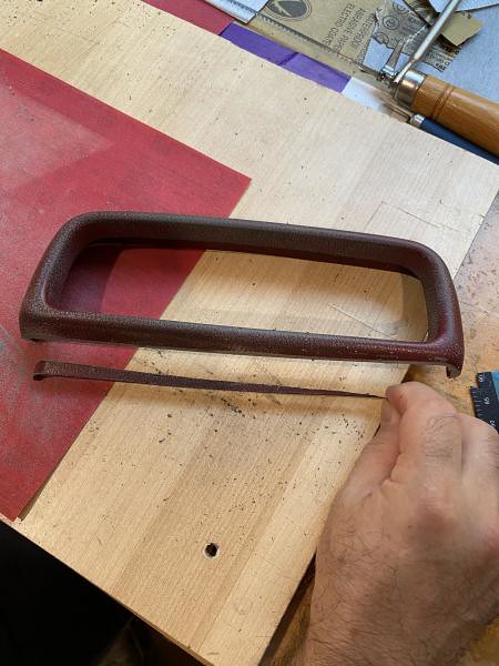
Next up was making the slope for the front section of the plastic case. The slope I had to make was the opposite direction of what was already on it. To achieve this I used cut one the pieces I had cut from making the back flat. I took the strip of plastic and cut out a triangle with the approximate slope of my dash and used a hair dryer to bend the plastic to follow the curve of the case. I then epoxied it to the bottom.

Now the next part took a whole lot of trial and error with my grandfather to get right but we finally figured out the best way to do it. We had to get the walls of the case to follow the shape of the dash to sit flush on it. We tried a lot of techniques to trace out the shape and hand sand it down and got pretty close, but not perfect. We ended up figuring out the best way to do it was using the same aluminum foil we used to build the walls. This time we put aluminum foil along the top of the dash where the unit would sit. We marked where on the final would be the final position of the inclinometer. We then mixed more epoxy and spread it out over the bottom edge of the entire case and stamped it on the dash. The epoxy took the exact shape of the dash and because of the aluminum foil was pretty easy to take off without damaging the case or the dashboard. Afterwards the overfilled epoxy was cut and any gaps were filled with a little more epoxy, then it was bondoed and sanded until smooth. Finally the unit was painted and ready for install.
The dash stamping method worked really well and the whole unit sits almost entirely flush with dash.


Finally to install the unit I had to modify the original mounting plate it came with. I had to use a dremel to the back end off a little so it fit into the modified case. The mount also had two threaded studs which were not going to be tall enough since the whole case got taller. I had to cut these studs off with a dremel and drill and tap two threaded hols in their place. I put two longer bolts into these holes. From here I just made two holes into the dash. I didnt have one of those 90 degree drill chuck things so I ended up using a sharp punch to punch a pilot hole. Then using a drill bit to go down the soft bits, then using the same punch to puncture through the whole thing. I then enlarged the holes with a little bit bigger drill bit. Three holes were made (two for mounting and one for wires.) The mount was secured from underneath using two washers and two wingnuts.
The final step was the wiring. I decided to tap into the clock power for this. If you end up doing this don't make the same mistake I made. Use a multi meter to measure out the voltages of the pins on the clock harness. There will be two pins that measure 12v. One of these is for the time circuit, and one of these is for the display circuit. Make sure to use the pin for the display circuit because otherwise the unit will not turn off with the cars ignition. To check turn the car off and one of the 12v pins will read 0, this is the pin for the display circuit and is the one that should be used. I accidentally made this mistake and spliced into the wrong one. My battery died after 2 weeks of sitting because I had left the inclinometer light on lol.
That's about it, this was a long, but really fun project. Let me know what you guys think and if you have any questions.


 Wonder if it would fit into an empty FMU housing?


 Linear Mode


