This thread is a work in progress while I have time to add onto it with pics and what not….
Well, I will try to start a write up on doing the heads for a 1GRFE motor. I will upload photos and progrees as it comes back to my memory. Car is up and running and out of my hands to a happy sibling. It is very straight forward and surprisingly quick job all thing considered. We were quoted over 4k for the job by Toyota in CO Springs, after they told us we needed a new motor. When I first dug into the car I simply wanted to be educated with what tricks may be needed down the line, and is why I joined this site. I received little to no help and just figured it’s like any other motor rebuild, and was much easier than expected. Dealer quoted 22hrs of labor, I did this not being familiar with Toyota motors in well under half the time. It would take an intoxicated blindfolded inbred 22hours to do the job, so don’t feel turned away by the labor. It is not rocket science and with the correct tools, focus, good service manual, and patience anyone could do this. I have only seen one other individual do this on the entire net and post about it. He was doing a full rebuild, and after 3 different motors had a running car. \
I did not write this during the process, but from memory of doing the job post completion. Your manual will cover anything I missed.
First off, go grab a copy of a service manual, they are available for free online. I used one for the 2003, and to be honest these motors changed very little minus more electronic BS they added all the way to 2009. Located here:
Service Manual Download Links.
Second order a 10mm Bihex tool now, so you have it when you need to pull the head bolts, do not use a tri square, you will be drilling out stripped head studs and likely cracking a head, or metal shaving into your motor. I have read many threads of this happening and why risk it over a 22 dollar tool. You can go with arp studs on reassembly if you want to get rid of the Bi hex, but I couldn't justify twice the cost on a stock motor that does not need it. Yes on a 1000hp diesel, a low hp gasser v6…no.
Third, order a complete OE gasket kit from Toyota. I found mine from a dealer in Texas for $230 shipped off ebay. All OE parts, not the aftermarket crap (you will regret it). Kit came with head gaskets, valve seals, all applicable o rings, intake manifold gasket, head manifold gasket, exhaust manifold gaskets, valve cover gaskets, header/collector gaskets, front cover orings, oil adapter, water pump gasket, cooler orings and gaskets, and literally everything you need to do a rebuild and then some. I did not use all since I was not rebuilding absolutely everything, and when removing the entire top end, removing smaller parts in sequence was not necessary. If you want to get some high end cometic HGs, go for it. Not necessary though.
Link to ebay kit I bought:
http://www.ebay.com/itm/Toyota-Tacom...b9a0a1&vxp=mtr
Royal South Toyota is who I bought our stuff from.
Fourth find a good reputable shop who can mill your heads and check your valves. If you end up doing a full valve job, look to spend close to a grand on your heads having to replace guides, and the lash cups Toyota uses.
Fifth – Make it easy grab a box of zip locks to label bolts/fittings as they come off. Makes life easier when reassembling, left over bolts is not a good thing!
Sixth - Go spray your exhaust manifold nuts and lower collector bolt/nut with penetrating oil so when you get to that point, life is easy.
*First pull the lower two splash panels off the car, there are 4 bolts for each, the front panel is below the radiator, and the mid panel is below the pan. Its a short and easy process and makes early progress feel quick!
To start off, drain the radiator. Unbolt the 4 bolts that hold the rubber bushings to your core support, disconnect you lower and upper hoses, and remove the 4 nuts on the fan. Remove your two tranny cooler lines. You then can easily lift the fan and radiator out as one piece.
*While the radiator is draining, remove your battery, if either of these steps have you stumped, I'd reconsider this job and at least call a mechanically inclined friend :-)
*The next steps can be done in any given order, but I chose to pull all the crap off the top side of the motor first before accessories on the front cover. Remove the Toyota cowl on top(2 nuts and 2 bolts) *Remove the supports from the intake to the head.
*Unclip and remove the air box and pull it out of the way towards the fender.
*Remove the other half of the air box, all that holds this down are 2 bolts to the intake, a CCV hose, and the clamp to the MAF. She will pop right off.
*Next pull the plastic intake manifold- If I remember correctly there are only 4 or 6 hex head bolts holding this to the head manifold dead center in the motor. Unplug your sensors, vac lines, water bypass hoses, and remove supporting bracketry. You will see the gasket to be replaced upon reassembly. This is all covered in step 5 here:
http://4runnerclub.com/i/4r_files/fs...ft_removal.pdf
*Next pull your coil packs, there are (6) 10mm head bolts that hold all (6) packs to the valve cover. Unclip and label each plug, remove the bolt and pull the pack. The main harness will only allow for these to be reininstalled a plugged in the correct way. step 6 here
http://4runnerclub.com/i/4r_files/fs...ft_removal.pdf
*You can proceed to do your valve covers next, but I waited till later simply to keep any serious crud to fall into the motor. I however pulled the VC off to inspect the cams/ for any serious visible damage, then put them back on for the rest of the disassembly.
Go ahead and remove the lower intake manifold from the heads themselves, to do so unbolt the fuel rail, unclip the fuel delivery and return fittings, and remove the rail as one piece with the injectors. You then can access the bolts from the top of the motor, they hold the manifold to the heads. I can’t remember the exact quantity, but I believe it was 10 bolts that need to be removed, pretty sure the heads were 12mm. Once free give it a good wiggle and it will pop right off. See the service manual for a step by step breakdown of this if my wordding is as clear as mud.
Below you will see the circulation bypass piping for the cooling system, this is probably the biggest pain to pull on the entire motor if you have big ol meat hooks like myself. Accessing the 6 bolts on the firewall side it a pain to get off, and much more so to reinstall. The caps are 10mm on the bolts. Move all 3 bolts on both heads for a total of 6. Remove the heater hose and sensor plug and you can slowly prey with ease past the seal of the oring to get this sucker off. I used a quarter drive and 10mm deep on reinstall. On the front side of the motor you will see a nearly identical piece with a few bypass 3/8 ID(?)hoses that were removed from the intake. It will also have 10mm and 12mm bolts that will need to be removed from the front cover. There is an O ring that seals each unit from the main piping that splits the heads, don't forget to replace and lube this upon reinstall, you will be provided these in your new gasket kit. There are 4 10mm bolts down the middle of the block holding the remaining piping, remove all 4 and pull the tire unit out, after popping off the rear half. You will see the two triangular gaskets that will need to be replaced upon reinstall. They only go on one way. Looking back on it, I'm pretty darn sure this could be removed with the heads, but I am not positive. possible,? probably, easier? yes, an option for reinstall..nope. I actually pulled them after I pulled the front cover, but put this up here since it would have been much smarter to do so at this point.
You can work the top part of the motor or move to all your accesories on the front cover. I pulled all of the front off next...
I wills say having an electric low torque impact will save you a shit ton of time over reassembly and disassembly through this process, I retorqued ever bolt on the motor that was removed, but its up to you and only a suggestion.
*Remove your serpentine belt, not sure how else to word it, but loosen your tensioner(lh direction to tighten pulley/loosen tension to remove belt) and pull the belt off taking note of original orientation if you don't have a manual during reinstall.
*Remove your filter bypass front the front cover, I removed the filter, then remove your 2 bolts securing the unit to the cover, 12mm caps I believe. I will make note, from the pics I did this first before removing the Cooling bypass piping, When I reinstalled the filter housing/bypass unit, I had to pop the thermostat housing off to properly align it. Not sure how i removed it without this issue, but just forwarning down the road.... either install the front coolant housing after installing this component, or simply pull the thermostat, install oil filter housing,and replace the gasket on the thermostat housing and reinstall...takes a matter of minutes.
* Next remove the water pump, this is very straight forward by removing the 10mm and 12mm cap bolts out of the front cover. Depending on mileage it may not be a bad time to replace the pump. Local parts stores carry them for very cheap, but may not last as long as the one in there currently. I ordered an OE pump from the same dealer out of Texas on Ebay for 190$ shipped. I won't even say the horrid price the dealer here locally wanted.
Pump ordered from royal South Toyota:
http://www.ebay.com/itm/Toyota-Tacom...805e60&vxp=mtr
* On to your drive pulleys, there are four idler pulleys for the serpentine. I labeled them upper an lower for each side of the block, and the tensioner pulley. There are number designations on each pulley that can be referenced in the manual if you forget, but just label the damn things and save yourself time. Remember your tensioner is left hand thread.
* Next pull your alternator. I could see this being a PITA to replace as well with everything assembled in the car, may be a good one to replace now and keep the stocker for a spare. Needed, no, worth your time now vs paying god awful labor rates at the dealership? That's up to you... That being said, hers was an OEM unit with 22k on it so no reason to do so. Once again There are two bolts holding it in, before removing pull you charge wire cover/cap and remove the 12mm nut that runs to your positive terrminal on the battery(now removed). Also remove the plug to the regulator on top of the alternator, this is a clip fit plug. Now remove the two bolts completely and pull your alternator
I will note, pulling the front wheels off may create better access to some of these components.
*Next I pulled the AC compressor, unplug your harness to the switch, then its very easy as there are 4 long bolts, that once removed allow you to pull the compressor out of the way. I did not detach anything else from the compressor, and simply moved it aside.
*Next you can remove the tensioner \, If my memory serves me right there are 3 longer 12mm capped bolts that bolt to the FC and short block, there is a shorter bolt that comes up from the pan side. Remove the 4 of them and the tensioner assembly will come right off, reference the manual for this step, as my memory is a bit cloudy. While your down there for the lower tensioner bolt, go ahead and pull the 4 pan bolts that hold the pan to the front cover. The engineers at Toyota were cool and notched the subframe for easy access to these, as some cars require the subframe to be removed :-(
*Now move to the passenger side of the car, All that is sitting over here is your power steering pump. Her pump was in bad shape and had a cracked pulley. To remove the pump pull the resrvoir hose off and let drain, remove you lines going to the rack and pinion. The upper line uses a 17mm if I remember correctly to remove the inlet hose. Take note there are brass washers on either side of the hose eyelet and banjo bolt, to create a proper seal. Replace these on reinstall to be sure of a no leak line, but many reuse them. Our new pump came with them. Lastly pull the two mounting bolts for the pump. You can rotate the pulley to use an extension through the pulley openings to remove them.
*Remove each side exhaust manifold. There are 6 nuts that need to be removed on each side. Before popping off each header, go below the vehicle and remove the collector piping on each side, there will be two nuts on each side. Unclip the O2 sensor plugs so the wiring is not stressed during removal. I also removed the bracket bolts to allow for extra movement in each header. The joint and bracket is right below the upper CAT converter. There is a brass donut gasket on each side that will be replaced during reinstall, and it is included in the master gasket kit. I wired each manifold to the side of the vehicle to keep it out of the way rather than removing each upper manifold. More room than needed!
I may not have said it during the removal of each component, but make sure to unplug each sensor and label it if need be. I only had to label a couple, but be cognitive of pulling the harness, mounting clips, and bracketry out of the way.
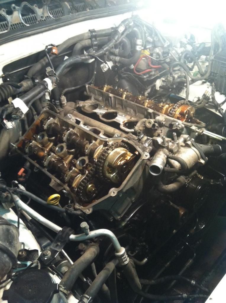
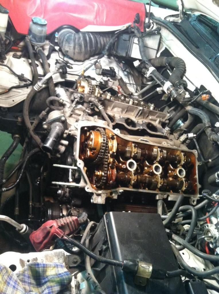
* Well now we can get to the fun part where progress is seen quickly. Remove your valve cover bolts from each side. Take not of the differet shank lengths and make sure to use the same bolts upon reinstallation. This will go fairly quick for each side. Pop your VCs off and go put them in a parts washer to clean any residue as my sisters had more than I like to see.
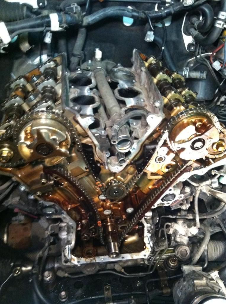
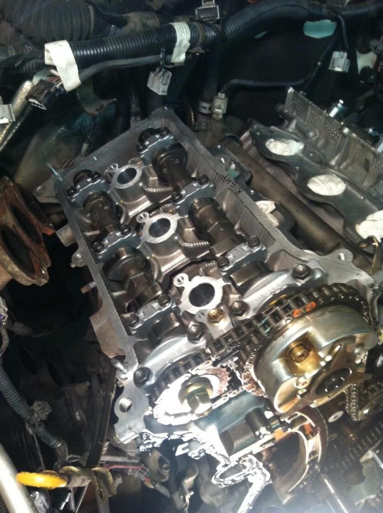
* Take a moment to get acquainted with the orientation of the cams and VVTI units in correlation to the timing marks and cam chain. Reference your manual for this procedure, but rotate the crank to TDC. Your timing marks on the VVTI units will match the correct position depicted in your service manual when your crank pulley lines up at 0. Take note of the orientation of the cam lobes as a back check for reassembly. Your service manual will depict the correct orientation, but I took a few pics shown below of the proper orientation to reference. The timing marks are hard to see, but reference your manual for proper orientation. I did not line up the colored links like you will in reassembly, as its not necessary for disassembly.
*Next pull the crank pulley, this is very easy as its the large bolt through the center of the pulley. I had a pneumatic wrench that popped it right off, double check your alignment to assure your TDC location. Slide your pulley off the keyway on the crank.
*Yu can go ahead and pull the front cover now. Remove the remianing 10mm and 12mm hex head bolts securing the cover to the block. The cover will take a bit of light prying at the designated points shown in the manual to break it free, but she will pop right off and slide off the crank. Go set it down and clean the inside thuroughly to remove any toasted residue.
* The next step is to remove your main drive chain. YOur manual will depict the lower tensioner, depress the tensioner allowing for slackin the chain. I used a sewing needle to hold the tensioner arm as depicted in the manual. not sure who has a 1mm pin sitting i their tool box, but I did not. You then can unbolt the two 10mm bolts holding the hydraulic tensioner to the block. Remove the remaining chain guides and take not of orientation. It can only go back together one way but snap a photo for reference. Once the remaing guides are removed the chain will be loose enough to slide off the VVTi units and lower crank sprocket. Bag your chain up. There is no need to remove the center idler sprocket.
*Now comes the fun part of busting the VVti bolts loose on either end on the cams. The retorque value was nothing near what it took to break these loose. Take note of cam orientation in the manual to not risk cracking the head. I modified a wrench to snugly fit the notching on the cam for this purpose. It took myself and uncle with cheater bars to break the sucker loose, I honestly was worried I'd snap something, and I did, my snap wrench. I can't believe how tight these bolts were, but all 4 finally were broken loose, and we finally removed the VVti units. I had the cams inspected in fear from all the torque there may have been an issue, luckily there wasn't.
• Once the VVtI units have been removed all you have left before tee ads pop off are the cams and head bolts. Each cam has 4 caps marked “E” and “I” for intake and exhaust. Do not interchange caps or cams and simply put it back together he way it came apart. Your service manual will instruct to loosen the cam cap bolts slightly and evenly throughout. They are torques very lightly and are very easy to break loose. Go through and pop all caps off each cam on either side to access your head bolts. Once you have gained access to the head bolts you are almost there.
• Grab that bi hex tool mentioned earlier on and start removing each stud in the sequence outlined in the manual. I broke ach loose about a quarter or eighth of a turn and then moved on to the next one. Once you have cracked tem all loose they are easy to finger out .
• Go ahead and wiggle/fry your head off in the designate pry points, it will take just a little bit of effort to crack it loose. You can then pull each side off and take a look . It was pretty evident once pulled where te gasket was leaking on the driver side on this motor. Even though very small, the channel can be seen in the picture below. If you really want to g ahead and clean the carbon off the top of he pistons, it will be carboned back up after the first drive or two, and is not really worth the time IMO. Inspect your cylinders while you are at it.
• Take both heads over o a bench and set front facing surface to front facing as pictured to pop the lobe caps off for the valves. I found it easiest to do it this way and paper down each cap and its clearance for reinstall. Your local machine shop can take care of this for you if you like, but there is no reason too. At this point if you are going to make a decision of a full valve job, this is the time to do so. Based upon our leak-down numbers there wasn’t need for one, and it drastically increases the cost of the headwork as you will likely be replacing all 24 cups from Toyota after the seats have been re-cut, big difference between 1-200$ and 8-1000$
• I did not do the headwork myself, and let a shop take care of it. Take them your valve seals that came in your gasket kit, and you should get them back ready to rock and roll.
• From here on out its pretty much an exact reverse of disassembly with a little bit of attention to procedure for reinstall. After you get your heads back, reinstall your caps in the same order. Clean the mating surfaces with a razor blade and good carb cleaner. Do this to the top and front surface of the block, and the front cover, there will be a ton of rolled over RTV that you can pluck off.
• Set you head gaskets down on either side of the block, make not of the number stamp and position to make sure you have put them on correctly. A a bit of Ultra Grey RTV up n the corer near the front of the motor as indicated in the manual, they reference seal packing…its just RTV with a Toyota stamp on it. I used my ultra Grey FORD crap.
• You can finally toss the heads back on, Line up the dowel pins and drop it on. Finger tighten your head head bolts in and torque according to the procedure in the manual. I torques them down in 4 series 2 of which I torqued to 80% of your final, then brought it up to the final, and the third series was to 90 degrees past final, and then 180 to your finish position. I’m sure you could have combined the first two without issue, but with aluminum head s and blocks I’m a bit OCD.
• Back to dropping the cams in… lube up each lobe and cap/seat with fresh oil, and get your matched cam/cap and install as noted in the manual with your arrow pointing in the right righting with the caps numbered in the correct sequence. Torque to spec lubing each bolt thread. Take not of the position of the front lobe on each cam, this is very important to follow the picture and position shown in the manual to insure the correct timing position. You may have to pop the secondary chain a couple teeth if it was moved at all in disassembly. Just pay attention to the manual and position, and this is very simple.
• After getting the cams in, place each side VVTI and secondary chain back on the appropriate cam and finger tighten each so they are snug and aligned on the guide pins. I then popped on the main Cam timing chain, guides, and tensioners in the same order I removed them. Be care of the colored links and the instruction of how to properly line each up to the timing marks on the VVTi and lower crank gear. I seemed to be about a half tooth off in tension and had to do a bit of rotating to get the chain to proper line with the crank gear in the correct marked position. If I remember correctly I removed a couple of the guides after the fact and one tensioner to provide a bit more slack. I also suggest keeping all of your tensioners fully compressed during this stage for ease of install. Once everything has been checked three times for proper alignment, take note to rotate approximately 90 degree CCW off TDC to torque the VVTI bolt and not risk cracking your heads. VVTI to the book spec. This is much easier than breaking them loose. Pay attention to you cam and crank positions through out this step and you will be fine.
• You are ready to pop the front cover back on. Reinstall the lower sump O-ring, align your new crank seal and guide ring to the notching on the crank, Make sure your surfaces are clean, I flushed the pa with a bit of cheap oil after a half can of carb cleaner to get any residual RTV bits that fell down. Apply adequate RTV and on the cover as shown in the manual and pop that sucker on. I added a bit more than was needed down at the pan surface. Slide it on and install all the necessary hardware.
• Form here on out putting it back together is the same as taking it apart. Everything goes on the same way as it came off. Use the same bolts and apply new gaskets, don’t skimp otherwise you will be doing some of it again. I soaked down either head with 1-2 quarts of oil, I drenched the chain and other components before throwing the valve covers on and adding the remaining oil. Necessary, probably not, but will prevent any dry/cold start damage. I’m weird and hit the cylinders with a bit of fogging oil as well. Gap and install new plugs, use OE plugs and don’t cheap, the copper ones will simply not last long, but they will burn a bit hotter. If you have any questions I am more than happy to answer them. Don’t forget the copper washers on the PS pump if you removed it!
• My only advice before firing the motor, fill up the sump tube from your filter adapter. This will insure that pump is fully primed when you crank it over, I know most of the channels drained while the cover was off. I’d also fill the filter a bit to soak the paper material, flip it over and spin on with very little splling. I cranked the motor a couple of times for a second or two making sure it didn’t fire, and let the fuel system prime. Foggng oil will assist keeping the cylinders lubed during this process. I let it sit and then cranked it over till she fired, took just a bit longer. Let it idle for a while and then drove it easy and listened for noises. Brought it back and inspected for any leaks or abnormal sounds. Drove the piss out of it the next day.Topped off the coolant after a few heat cycles, and se has been running strong for quite some time.
That is all I have!

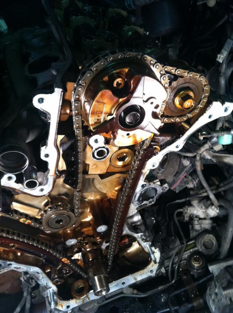
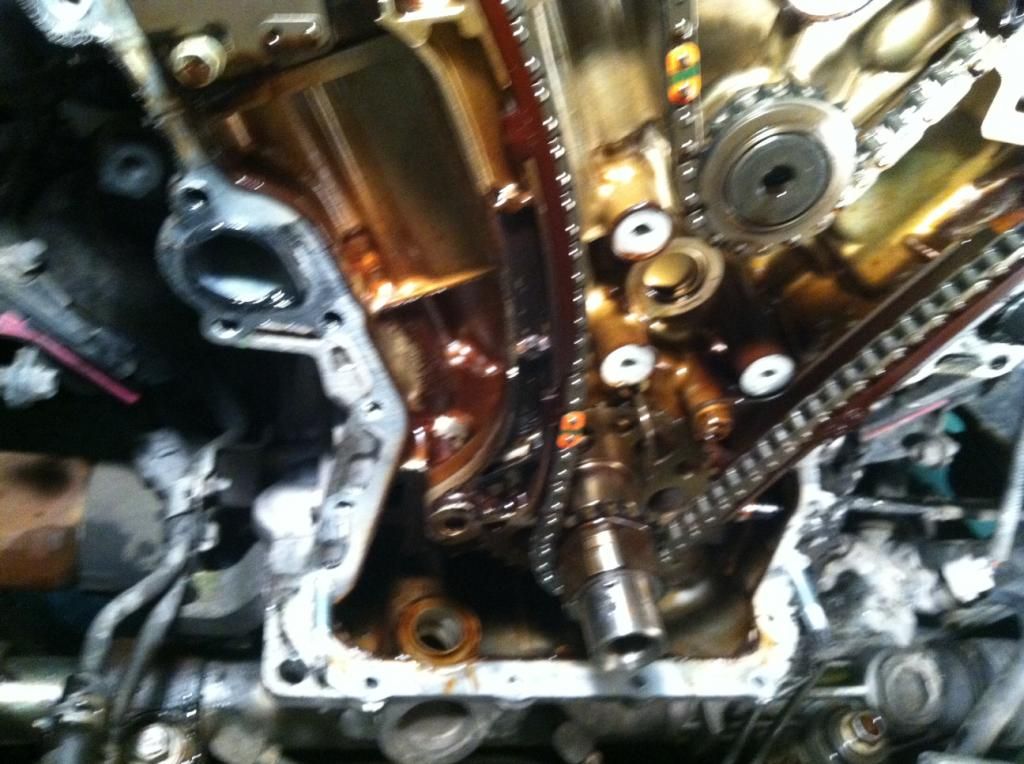
Above is a picture of the front cover removed prior to pulling the cams and timing chain.
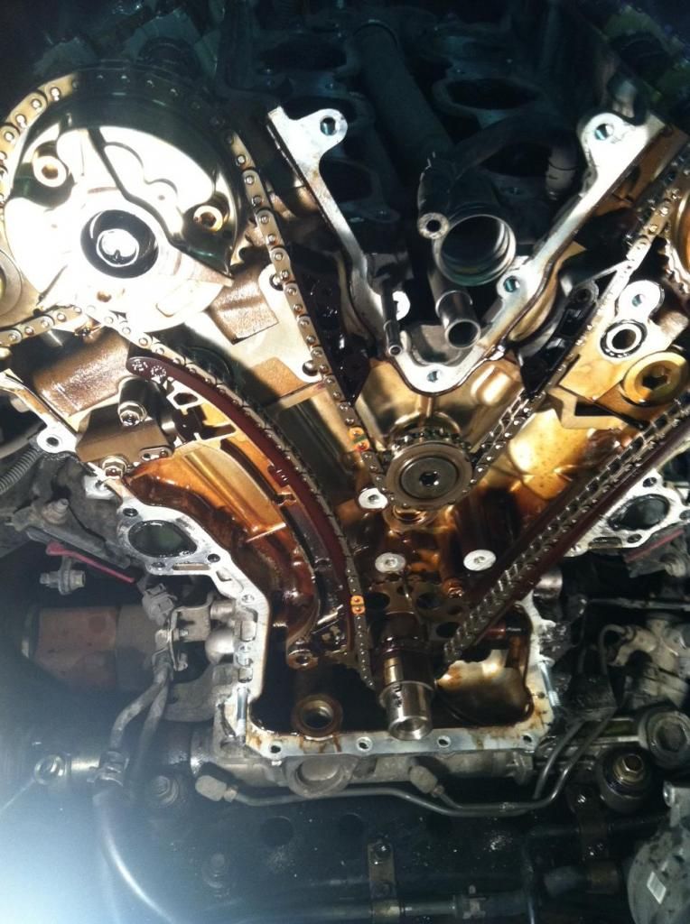
Another....
For reference of you forget what side VVt unit goes to which side.
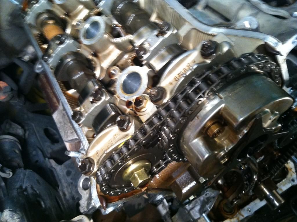
Pic of driver side timing marks at TDC, and cam lobe position before removal
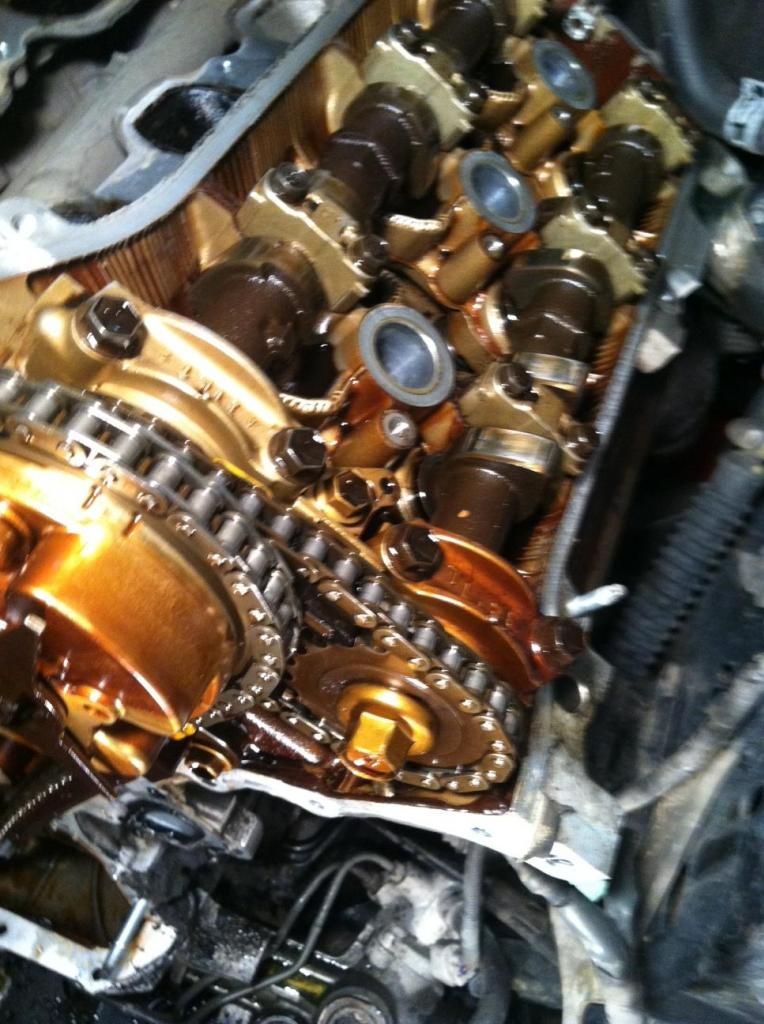
Pic of the driver side before removal. Timing marks and lobe position at TDC
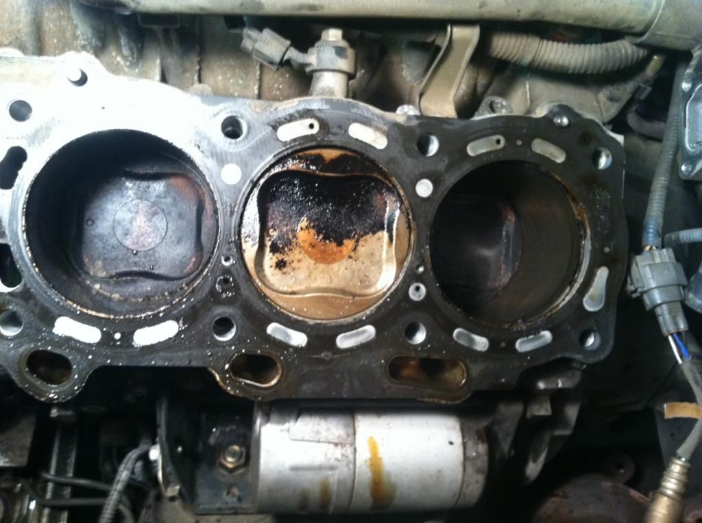
Yup that was the wet cylinder!
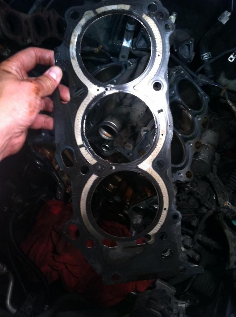
Tiny little leak caused all of this!
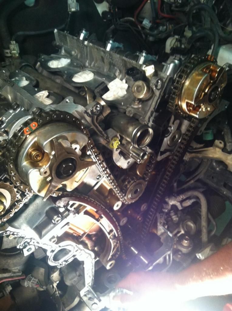
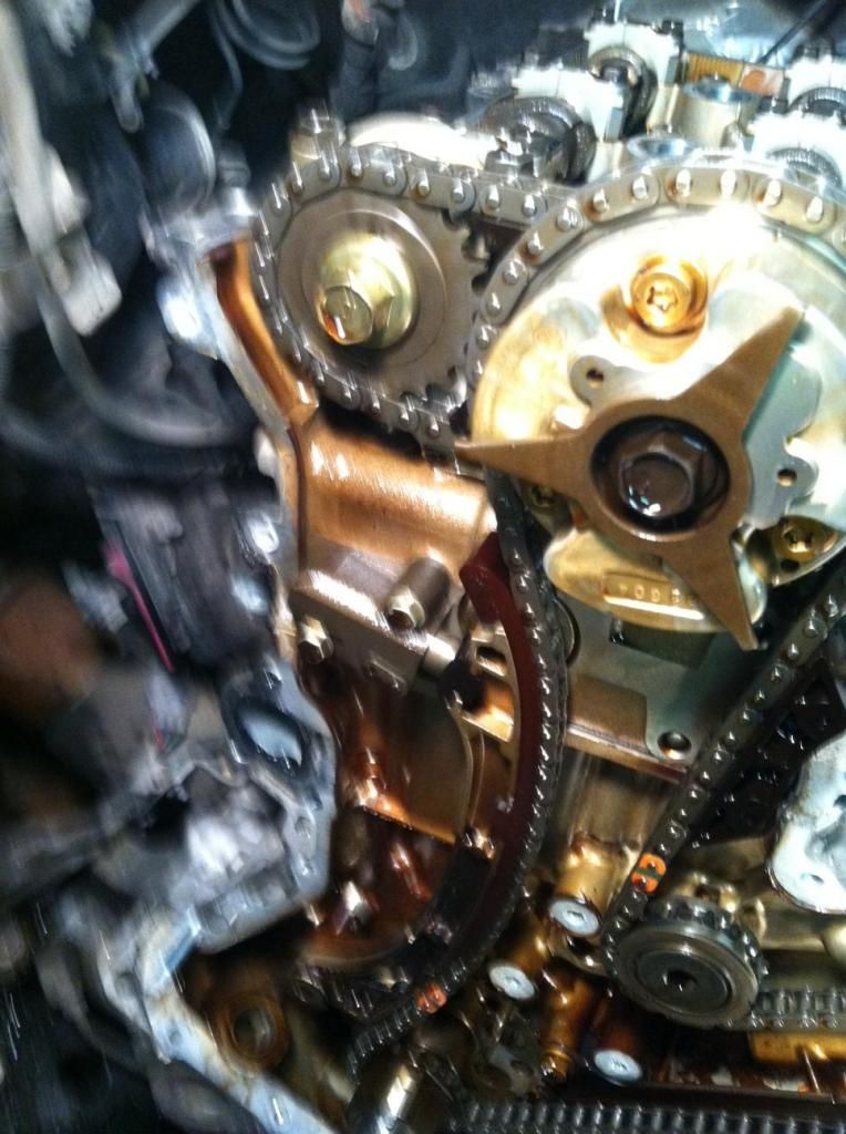
Pic of cam chain installed with all timing pmarks and links in the correct position.
Cam lobe position and timing marks upon re-install.
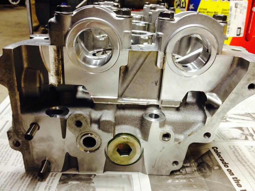
Cleaned up and ready to install..
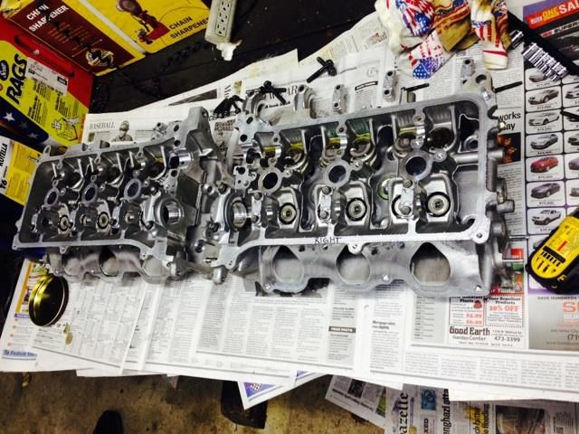
Process of dropping the old caps back in.
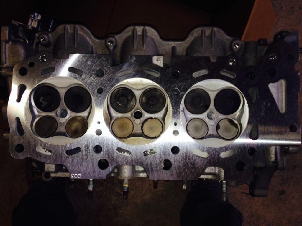
Removed 3 thousandths on both....


 )
)
 Linear Mode


