So for those of you who are not aware, when you change the physical tire size of your vehicle you will affect the speedometer's accuracy. For example a common tire upgrade on this forum is to go from the stock P265/65R17's (30.5") to LT285/70R17's (32.7") which comes to a 7% difference in diameter. This means that your speedometer reads 7% less than what you are actually doing (I found that at about 80mph I was doing 85mph or so.) You can figure out what the percentage difference is in your tires by using a tire calculator like the one on Tacoma World:
Tire Size Calculator - Compare Tire Sizes
There's a product called SpeedoHealer by Healtech Electronics (
HealTech Electronics Ltd. ? Smart Tech for your Ride ? SpeedoHealer v4) that corrects this issue in motorcycles (apparently digital speedometers in motorcycles are notoriously inaccurate), conveniently the VSS (Vehicle Speed Sensor) in motorcycles is the same in most automobiles. I want to thank 4Mudder on the Toyota120 forums for referring me to this product and his write up (
Speedometer correction - Toyota 120 Platforms Forum)
NOTE- You'll want to use the SpeedoHealer "Universal" kit as the wiring will match what I did.

Now I installed mine a bit differently than 4Mudder's and I figured I'd post how I did it in case others wanted to see other ideas for installation.
First things first lets get the wire colours of the SpeedoHealer v4 out of the way, I found this slightly confusing at first because they didn't show a diagram or table and instead used verbiage to somewhat describe what the wires did.
Red- 5v-12v Power Source
Black- Ground
White- VSS (Vehicle Speed Sensor) Input
Green- VSS Output
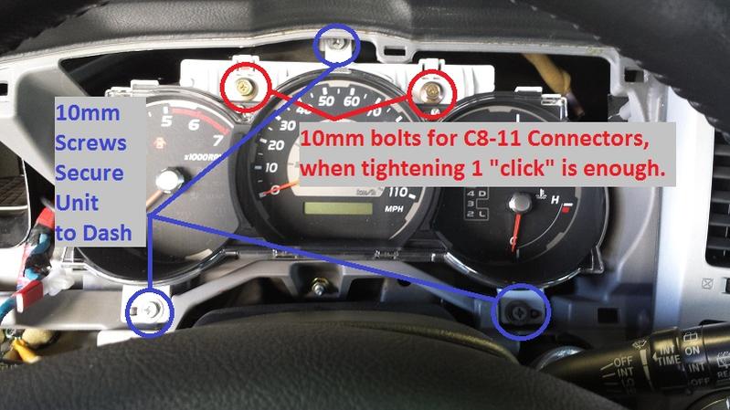
Now lets get the combination meter out of the vehicle so we can get to the wires. This is all straight forward, you'll find two 10mm bolts on the lower kick panel under the driver's side that need to be removed and everything else just pulls off with snap clips. The combination meter is held down by three 10mm screws that go into the dash and two 10mm bolts that secure the connectors to the combination meter as illustrated in the following picture. Do note that the gold 10mm bolts will "click" when tightened, you only need them to click once to have the connectors nice and tight when reinstalling.
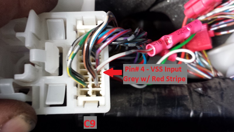
The next thing we need to do is determine what wires we're going to cut into, if you happen to have an EWD (Electrical Wiring Diagram) for 4th Gen you'll find (after digging a bit) that Pin#4 (Grey with Red Stripe wire) on Connector C9 is the VSS Input from the Skid Control ECU. You'll want to cut that off about an inch or two from the connector and splice the White wire to the end feeding from the Skid Control ECU and then splice the Green Wire into the end feeding into the combination meter, like so:

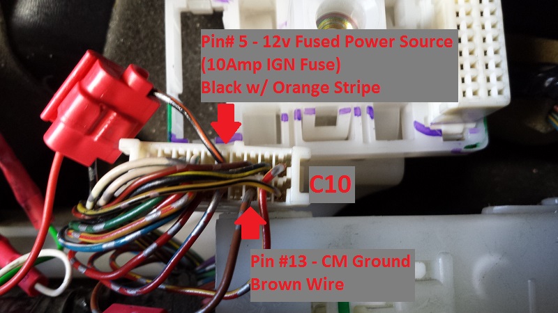
Now that we have the VSS signal taken care of, you'll want to get power and ground, this is mainly where I differed from 4Mudder's installation procedure. I figured that the unit is not drawing a significant amount of amperage to operate (as it just shifts the VSS signal by a calculated percentage) and thus took that gamble that it could be spliced into the combination meter's power supply (it was a gamble because I didn't have a small amp clamp to bench test its actual amperage draw and so I based my guess on experience.) I tapped into Pin# 5 (Black with Orange Stripe wire) of Connector C10, this is the 12v Fused Power Supply for the combination meter (the 10Amp IGN Fuse located under the dash) and then for ground I tapped Pin#13 (Solid Brown wire) on Connector C10 for the ground. Pin# 13 is what is referred to as a "Dirty Ground" which means it is used for many various functions such as the small motors for the speedo, tach, ect. and using this ground won't cause issues with sensor readings or computer function such as using a "Clean Ground" would.
I then routed my SpeedoHealer harness behind the dash bar and fuse block and to the actual SpeedoHealer unit which I stuck to the metal reinforcement plate for the kick panel. It comes with adhesive velcro tape and it perfectly fit between the fuse block and the metal panel right here.

Now the main reason I routed it here was for ease of access in case I ever needed to do anything with the unit. Where it is now is out of the way, but easily accessed; with the added bonus of looking almost factory (you all know how obsessed I get about that!

)

After its all nice and installed, just follow the instructions on the paperwork that comes with it to set your SpeedoHealer and enjoy a now accurate speedometer! I will also note that the SpeedoHealer v4 comes with a dual memory function, which means you can switch between two different settings; I would assume this is a nice bonus for those of you who run smaller street tires and larger off-road/winter tires.


 Linear Mode


