Quote:
Originally Posted by Louisiana Overland

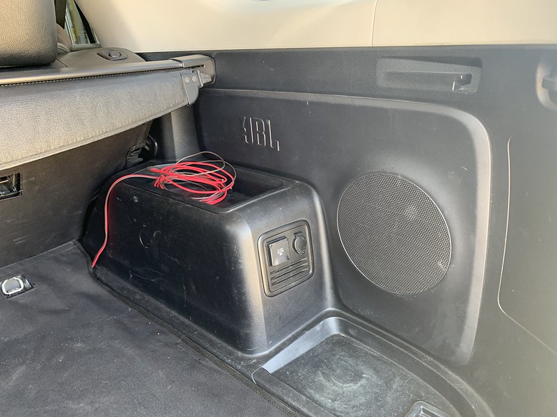
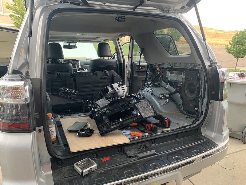
I pulled up the rear floor and carpet and made my own plate with 3/4 irch ply and then painted it with bedliner. For power, I used the ARB install kit. If you alreAdy ran wire you could skip the kit and buy just the ARB receptacle. It works with my dometic cfx50 cord and is threaded to ensure it will not unplug due to vibration. I mounted the receptacle near the front of the wheel well leaving room to clear the fridge/slide and rear of rear seat. This is on the passenger side. I run an odessey 34R with the hkb diode and carry a lithium jump pack for back up.
Im sure you are aware, but for the sake of someone just researching this.... the fridge has several settings to force it to shut off at certain voltages to prevent totally draining the battery. This is especially important on a single battery set up like mine. This prevents you being stranded. For this reason you should not use the factory wiring by converting the rear outlet to always on. The wiring is too small to carry full voltage at that length and your fridge will cut off prematurely. I ran 2awg to a distribution block under the drivers seat for audio gear and tapped into that for the fridge wiring. Ill be tieing in there again soon to install a HAM radio.
|
I have my whole electrical system sorted out at this point. My objective was to design and build a dual battery system that is permanently isolated from the starter battery, charged by solar, DC-DC charger, or an AC shore power hook up, protected by a low voltage disconnect and supplies power to a custom power distribution module which operates any and all non-OEM electrical components, most of which are controlled by a custom switch panel in the dash. Plus I wanted to make and incorporate a plug and play roof top tent electrical box that will provide a tent power outlet, red tent interior lights (red doesnt attract bugs), white tent interior lights, and controls for the roof rack mounted exterior camping lights.
I started with planning the project. I researched everything, the individual components, amperage requirements, amperage limits of the connectors, waterproofing ratings, quality, durability, compatibility, bang for your buck value, expected life, etc, etc, etc. I wanted to determine what pieces would best fit my intended use. From there I made a wiring diagram.

This was basically my blueprint to get all the ideas in my head on paper. I wanted to confirm everything I was planing was plausible and will work the way I had envisioned. When I was satisfied in the layout and everything in theory should be functional I used it as a reference while I built it all out. I wanted to do a nice clean installation once, the first time and a good diagram was a key factor in that. Plus its nice to be able to troubleshoot with ease down the line if ever necessary. I got everything listed out - connectors, which wire goes to which terminal, what the wires are for, what color wiring each system uses, relay pin designations, the parts and pieces Im going to use for assembly, the weakest link in each circuit in terms of amperage limitations so I could fuse each thing safely and appropriately. Ive never been a fan of popping a hood and seeing a rats nest disaster of wires, attention to detail has always been important to me.
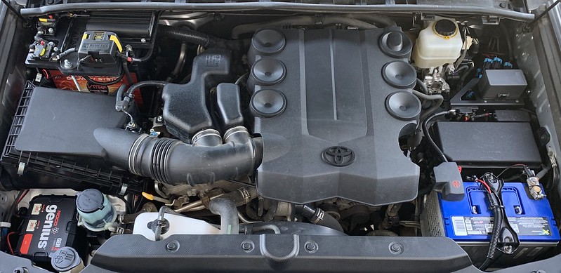
For the dual battery setup there's a power wire from the positive terminal of an X2 Power (rebranded Northstar for Batteries Plus) BCI Group 24F 76ah AGM dual purpose deep cycle starter battery to a Blue Sea 40 amp circuit breaker. From the circuit breaker, the power wire runs to the red battery input wire on the RedArc DC-DC 12 volt 25 amp dual input (DC and solar) charger. The brown power output wire on the RedArc goes to another BlueSea 40 amp circuit breaker. From the circuit breaker, a power wire goes to the positive terminal of the Vmax Charge Tanks BCI Group 24 SLR85 85ah deep cycle accessory battery mounted in a C4 Fabrication passenger side firewall battery tray. A power wire from the accessory battery goes to a BlueSea 80 amp circuit breaker. From the circuit breaker, a power wire runs to a BlueSea low voltage disconnect. From the low voltage disconnect, a power wire runs to the positive terminal on the power distribution module. The power distribution module ground wire connects to the negative terminal of the starter battery. The accessory battery negative terminal has a cable to chassis ground and a wire to the ground the low voltage disconnect. The blue wire from the RedArc goes to an ignition on reference under the dash. The orange (charge profile) and green (remote indicator led) wires from the RedArc are not being utilized in my application and are terminated and weather sealed. The yellow wire off the RedArc is capped and weather sealed, it will be used as the solar input at a later date.

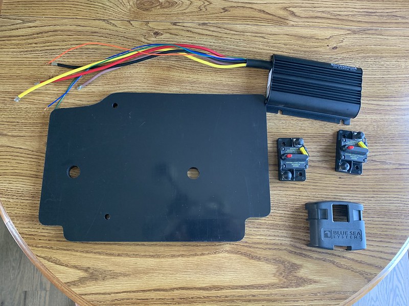

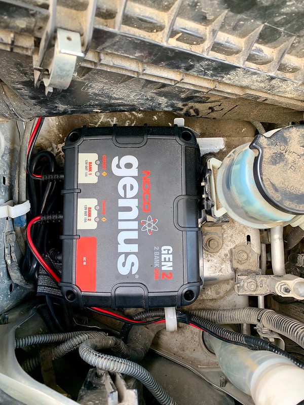
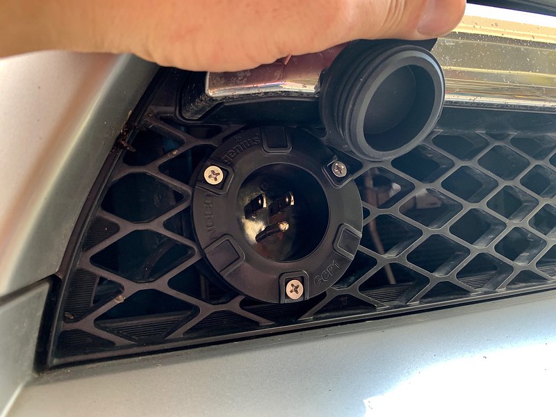
I installed an onboard waterproof NOCO Genius Gen 2 dual bank 20 amp charger. It connects to both of the batteries and when plugged into shore power (normal house AC outlet in the front grill) it will smart charge and maintain each battery individually while supplying up to 10 amps per battery as needed. I can ensure the batteries are topped up before leaving on a trip and if we're at a campground or something with an electrical hookup I can run everything in the truck by plugging it into an extension cord. I made the mounting plate out of half inch thick HDPE for most of the components to sit on top of the accessory battery, and I cut up the modified the hold down to clear wiring laid out in the positions I wanted them. I made a second mounting bracket for the onboard AC charger behind the passenger headlight.
For the Power Distribution Module I started with a Bussman 10 circuit power distribution module mounted in a Shrockworks bracket. I modified 2 BlueSea bus bars to fit for ground points on each circuit. There are 5 fused circuits and 5 relayed circuits. I wired it all to be plug and play using Metri-Pack 280 Series, Delphi Weather-Pack, and Molex Mini-Fit Jr connector housings, terminals, and seals depending on the circuit and intended use, and its all type TXL Primary Wiring (OEM Specification: Ford M1L-123A, Chrysler MS-8288, SAE J-1128), with marine grade dual wall adhesive lined heat shrink, ISO 280 35 amp micro relays, and ATC blade fuses.


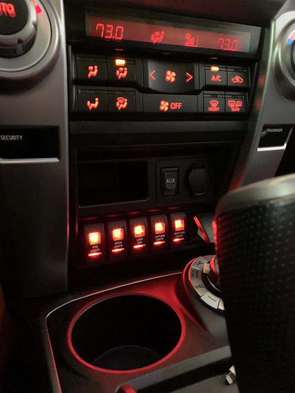
For a Switch Panel I picked up a new OEM dash compartment for a 2014+ (without the door), custom Contura II switches, a Blue Sea 1039 dual USB fast charger, and a blank mounting panel to install them in, and made it all fit. The switch backlighting is a match to the factory dashboard backlighting.


For the roof rack camping lights I wired them with a connector right at the front along the inside edge of the lower portion of the side rails. I can unplug the connection on the passenger side and plug in the roof top tent electrical box inline. With the right side light switch on the dash turned on it provides power and ground to the tent box which contains its own internal fuse box to run a power outlet, the interior lights, and control the exterior lights.


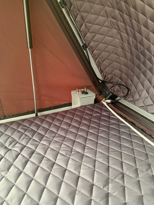

It's all together, weatherproofed, and fully functional. I performed voltage drops on each connection to verify everything is correct and it performed flawlessly over our first weekend camping trip with everything installed. All of the aftermarket lights and accessories are powered by the second battery with the lone exception of the interior switch panel backlighting so the starter battery is not at any risk of being drawn down. While I ran the ignition reference wire for the RedArc to the interior. The red wire from the original post is ran to the back awaiting a hookup for the fridge. I have 2 more still unused circuits I pulled into the interior that I haven't decided what to do with yet - im thinking maybe a second row power outlet and possibly a small water pump (RV faucet) hook up from running fresh water.


 Linear Mode


