Be_Originals (Budget) Projects Thread

Be_Original

New member
In an effort to get motivated to continue with my build I figured it would be worthwhile to share my planned rear bumper, rock slider and front bumper builds. Don't expect this to be overnight builds as my work schedule consumes my life but I hope to have each build done within a months time. Enjoy.
 
Register to hide this ad
Rear bumper: Bolt on application. 3/16" steel plate, 2 shackle mounts with shackles and a tire carrier.

I made the mistake of removing my rear bumper close to year ago and although I would like to make excuses I have just been straight lazy and never initiated my rear bumper build. With a change in jobs and access to a awesome shop and equipment I started.

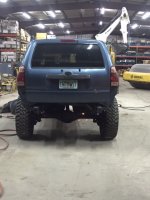
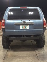
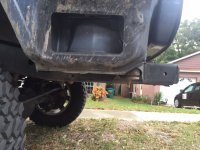
JUNE 2015- Removed stock bumper, side air vents, cross member on rear end of frame, hitch/receiver, all spare tire components and cut the exhaust tip along with resonator. I can post pictures of how it looked before everything was removed if you're interested as well.
IMG_1981.JPG
IMG_2170.JPG

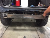
4-1-16- Finished filling in vent holes with 1/16" stainless steel plate (***** to weld) had it on B heat setting at 150-175 feed on a tig welder, cut off the end caps of the rear frame and filled in with 3/16" plate and welded in a new straight cross member 3/16" wall thickness.
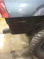
IMG_2747.JPG
IMG_2748.JPG
IMG_2749.JPG

4-3-16- Ordered bumper accessories which include weld on shackle mounts (Ebay specials), tire carrier swing out kit (4x Innovations) and a pull action clamp (Destaco 341R).
The toughest item to look for was the tire swing out kit. Initially I was just going to buy a heavy duty weld on roller bearing hinge (used for large/heavy fences) seen here>> http://www.hooverfence.com/ornamental/hardware/badass-hinges-steel.htm
After review I just went ahead and bought a dedicated kit, I also didn't want to mess with zinc coating on the gate hinges and welding. Here is a list of companies that offer tire swing out kits:
4X Innovations
A to Z Fabrication
Competition 4x4
EMS Off-road
Iron Pig Offroad

 

Attachments

  • IMG_1981.JPG
    IMG_1981.JPG
    127.4 KB · Views: 261
  • IMG_2748.JPG
    IMG_2748.JPG
    100.9 KB · Views: 312
  • IMG_2170.JPG
    IMG_2170.JPG
    90.9 KB · Views: 291
  • IMG_2747.JPG
    IMG_2747.JPG
    90 KB · Views: 306
  • IMG_2749.JPG
    IMG_2749.JPG
    77.7 KB · Views: 275
Last edited:
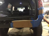
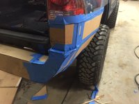
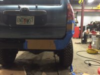
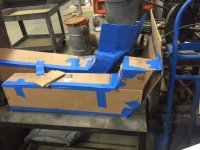
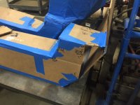
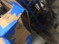
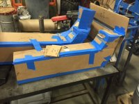
4-8-16: Today was pretty productive. With the help of a friend we made a ROUGH draft template of the rear bumper using cardboard and painters tape. While it was very fun and educational I did not realize how much math was involved in building a bumper and assume it will get more in depth once I get closer to the final draft before the actual build. The hardest part was joining the rear and side parts of the bumper.
Hard to see the detail and angles in the pictures:
IMG_2172.JPG
IMG_2176.JPG
IMG_2179.JPG

I took measurements of the pieces that made up the bumper and have the angles based on top and bottom measurements of such pieces. I plan to cut cardboard again with more detail and mocking it up, this may be done two more times until the correct measurements and angles are retrieved. I really don't want it to come out looking like a**.

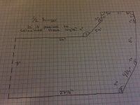
4-15-16: Not much to report other than rebuilding the template using sharper cuts and more precise measurements. This helped me visualize the corners in a more defined manner. Most of all my old, rough measurements were off by 3/4". I now know that I will most likely have to free hand two triangular filler plates to fill a void on the rear bottom corners to join the side and rear. On a side note bare with me as I said this build would take a month but I am only working on it after work on Fridays. Realistic ETC on this build is probably mid May. I will post a picture for those of you who are math geniuses to help solve some angles on the rear main plate.
Next I plan to purchase either 3/16" wood or plastic and build a full bumper template before transferring to metal.
IMG_2847.JPG

IMG_2848.JPG

IMG_2849.JPG

IMG_2850.JPG
IMG_2853.JPG
 

Attachments

  • IMG_2847.JPG
    IMG_2847.JPG
    113.5 KB · Views: 194
  • IMG_2848.JPG
    IMG_2848.JPG
    105 KB · Views: 149
  • IMG_2849.JPG
    IMG_2849.JPG
    93.7 KB · Views: 206
  • IMG_2850.JPG
    IMG_2850.JPG
    119 KB · Views: 148
  • IMG_2172.JPG
    IMG_2172.JPG
    84.4 KB · Views: 186
  • IMG_2176.JPG
    IMG_2176.JPG
    91.9 KB · Views: 188
  • IMG_2179.JPG
    IMG_2179.JPG
    85.9 KB · Views: 212
  • IMG_2853.JPG
    IMG_2853.JPG
    99.4 KB · Views: 199
Last edited:
4-16-16: Went to the local metal/surplus store, Acme Industrial Surplus in Sanford, FL for you locals, and picked up a 4'x4' 3/16" plastic sheet. This will be used for my final template....promise. This will ensure that the measurements are final and solid. I am waiting for a buddy of mine to give me contact info on a shop that has a water jet cnc machine to get quotes on cutting the final steel sheet metal pieces. Last resort is torch and grinder:dizzy:

4-22-16 - to next week: Friday night sucked. Worked on cutting the pieces of plastic for the last template. The black and decker jig saw I borrowed from a coworker is not meant for heavy use and kept overheating, so needless to say it took 3 hours to cut 13 pieces of my bumper. I then didnt have any adhesive on hand to put the bumper together so decided to call it a night (its about 10:45PM). Drive towards the front gate at work and hear a clicking/grinding sound. Looked for an hour trying to figure out what it was, finally jacked the truck up and drivers side wheel hub had about 3/4" of play up and down! Wheel hub assemblies on order from [MENTION=100129]nj636[/MENTION]. Updates will come along the week as I put the bumper together.
 
Last edited:

Members online

Forum statistics

Threads
278,310
Messages
3,554,080
Members
248,016
Latest member
Advally Service

Trending content

Back
Top