RAD4Runner
Senior Member
(I'm posting this here so it will be easier to refer to, rather than re-typing explanation into various threads that need the explanation.)
Here's the 22RE-liable schematic:

Close-up of alternator pin-outs is here:

White "B" wire (heavy gauge) to the 80amp fuse
This is the battery charging wire.
From FSM:
With engine from idle to 2000RPM, Voltages at B should be:
13.9 to 15.1 V @25°C (77°F)
13.5 - 14.3V @115°C (239°F)
Not sure which temp it is. Could be battery temp. It affects electrolytic process.
WITH B-WIRE DISCONNECTED, measure resistance from screw terminal to ground. You should get Very high reading. Lots of Meg-ohms (Sorry I forgot how much mine read). If low, suspect bad rectifier (s).
White "S" to the 40amp (always-on) fuse
Tt should read as close to battery voltage as possible. This senses actual battery voltage and should be connected as close as possible to battery positive. It is merely spliced with the B wire near or at the junction of 80-Amp fuse and 80-Amp fusible link wire. Low "S" voltage means battery needs more charge so the regulator would increase output voltage. If "S" wire and or connection is bad it could lead to overcharging and charge fault error light would come on.
Red "IG" to the Engine fuse
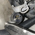
This provides field current to "seed" the charging. This should have steady 12V when ignition is on (coming from Engine fuse). If no 12V here or if this voltage is erratic or engine fuse blows, trace wiring back to Engine Fuse, to "E" battery positive wire from fuse block, and verify that your backup switch or wiring is not shorting to transmission body as shown here.
Yellow "L" to the Charge Warning Light
This should be near +battery voltage when alternator is working properly (B voltage 13.5V-15.1V). If there is a charing fault "L" will go low - approaching zero, and provide ground to negative side of the Charge Light causing it to come on.
(Unfortunately, it also provides ground to Brake Light and A/T Oil temp light- making it confusing to many.)
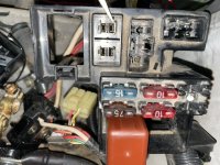
Most accessible place to measure "L" voltage is here:


ALTERNATOR HARNESS AND MORE VOLTAGE TESTS OF NORMALLY-FUNCTIONING CHARGING SYSTEM:
Here's the 22RE-liable schematic:
Close-up of alternator pin-outs is here:
White "B" wire (heavy gauge) to the 80amp fuse
This is the battery charging wire.
From FSM:
With engine from idle to 2000RPM, Voltages at B should be:
13.9 to 15.1 V @25°C (77°F)
13.5 - 14.3V @115°C (239°F)
Not sure which temp it is. Could be battery temp. It affects electrolytic process.
WITH B-WIRE DISCONNECTED, measure resistance from screw terminal to ground. You should get Very high reading. Lots of Meg-ohms (Sorry I forgot how much mine read). If low, suspect bad rectifier (s).
White "S" to the 40amp (always-on) fuse
Tt should read as close to battery voltage as possible. This senses actual battery voltage and should be connected as close as possible to battery positive. It is merely spliced with the B wire near or at the junction of 80-Amp fuse and 80-Amp fusible link wire. Low "S" voltage means battery needs more charge so the regulator would increase output voltage. If "S" wire and or connection is bad it could lead to overcharging and charge fault error light would come on.
Red "IG" to the Engine fuse
This provides field current to "seed" the charging. This should have steady 12V when ignition is on (coming from Engine fuse). If no 12V here or if this voltage is erratic or engine fuse blows, trace wiring back to Engine Fuse, to "E" battery positive wire from fuse block, and verify that your backup switch or wiring is not shorting to transmission body as shown here.
Yellow "L" to the Charge Warning Light
This should be near +battery voltage when alternator is working properly (B voltage 13.5V-15.1V). If there is a charing fault "L" will go low - approaching zero, and provide ground to negative side of the Charge Light causing it to come on.
(Unfortunately, it also provides ground to Brake Light and A/T Oil temp light- making it confusing to many.)
Most accessible place to measure "L" voltage is here:
ALTERNATOR HARNESS AND MORE VOLTAGE TESTS OF NORMALLY-FUNCTIONING CHARGING SYSTEM:
The engine compartment wiring harness has an "intermediate" connector along the left inner fender, near the power steering pump, shown below:
 Pin-outs are as follows:


Last edited: