Again. too many images, continued from above:
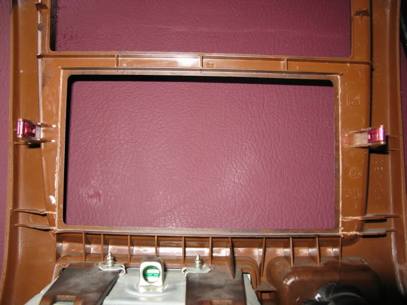
From there, I was actually able to get the dash trim almost completely locked into place over the stereo (it was sitting about 1/8” too far out). At this point, I’m thinking to myself, “Maybe I won’t have to trim so much of the dash trim bezel.” I sat there looking at it for awhile trying to figure out what to do next. The first thing is that the buttons were interfering with the dash trim bezel and making room for those would give me about another 1/32” of clearance. Figuring that if I had to trim the whole bezel anyway, I might as well try to clear the buttons first and see how it looked. I made a rough outline of the buttons on the bezel piece with a Sharpie, and then carefully trimmed openings for those with a file. There is a ridge of plastic right around the backside of the bezel edge that is about 1/4” wide. Here, the bezel is about 1/8” thick total. The next thing I did was to thin down the plastic near the edge of the bezel on the back. I used a file and carefully removed about half of the total thickness. After doing these two things, the dash trim bezel actually fit into place over the new stereo head unit!!!

It sits about 1/32” proud from the surface of the rest of the dash, but it does lock into place and you can’t see the crack unless you’re looking right at it from the side, which won’t be happening very often. At this point, I decided to leave well enough alone, and called it good. Since the plastic used in this dash panel is a medium brown color and not black, I touched up the visible areas I cut (stereo button cut-outs) and the backside a little with a black Sharpie, let it dry, then buffed with a napkin. Repeat 2x – 3x, and it matches pretty well; at least well enough you can’t tell the difference without getting pretty close up.
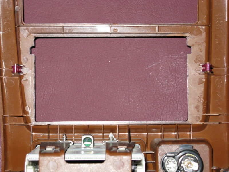
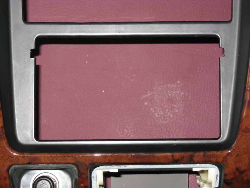
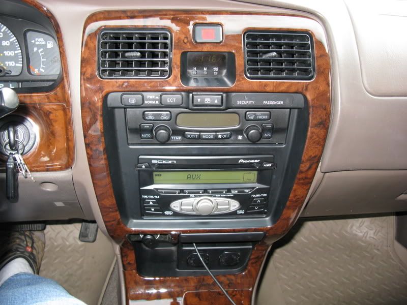
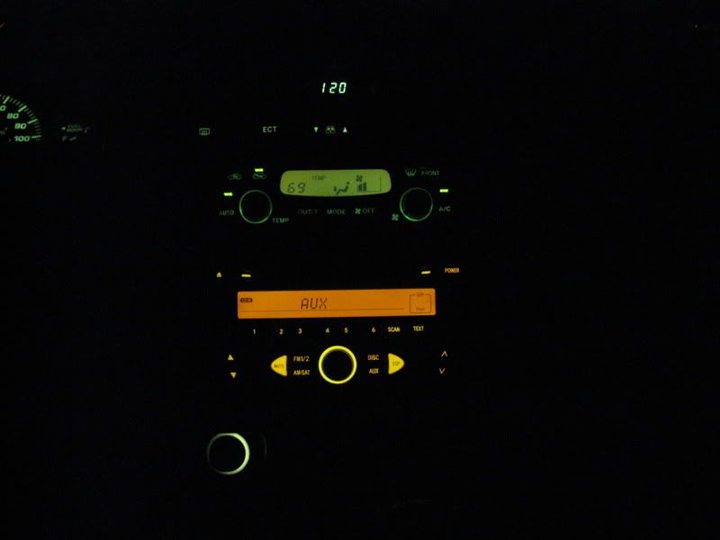
The final product turned out pretty well, and I decided the button cut-outs looked ok; at least better than trimming the whole sides of the bezel would probably look. You can see the cable for the Aux input sticking out from under the ashtray. I can roll the cable up and stick it under there out of sight when it is not in use.
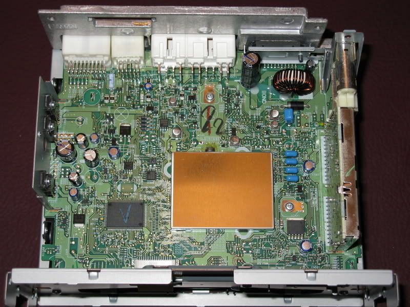
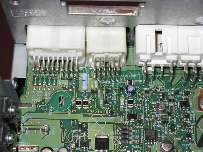
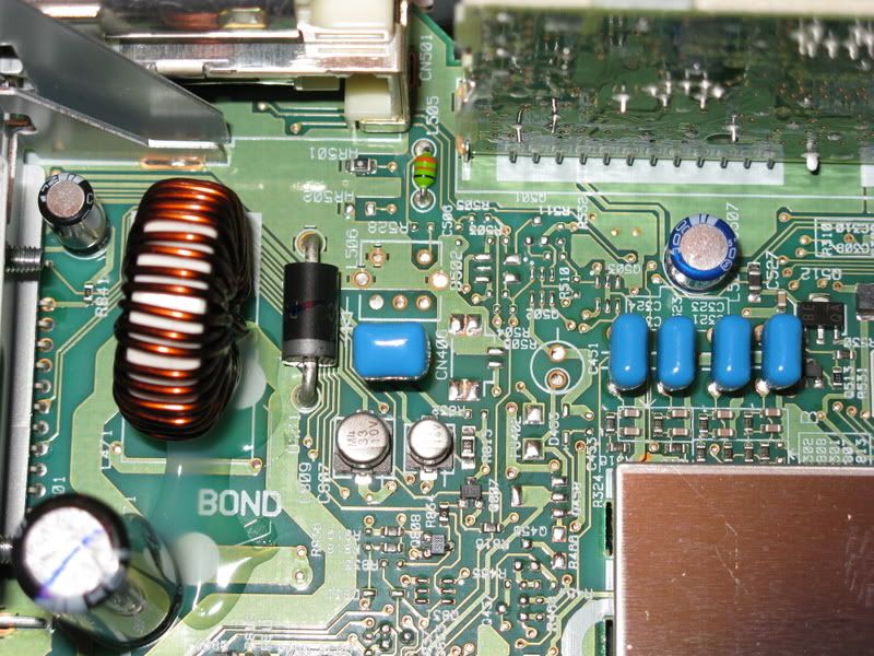
One final thing of note – you’ll see in the pic of the back of the stereo that I drilled an opening to get to the second antenna input. However, as someone else pointed out on somewhere (I think it was here), unfortunately the diversity tuner circuitry is not populated on the circuit board. I have noticed that radio reception is slightly worse than the factory stereo, which is probably why there was a diversity antenna in the first place. At least the receptacle gives you a good place to put the extra plug. Here are several pics of the stereo’s circuit board: