Got these items figured out:
- Why are there 3 connections on the variable resistor? Shouldn't there only be two?
There are multiple ways to wire a variable resistor depending on the performance desired, but you use wiper terminal + r1 to go from 0 to 20k and wiper terminal + r2 to go in reverse (20k to 0)
- Why is there no range listed for the variable resistor? It just says 20k ohm but shouldn't it be xxx - 20k ohm?
The range is 0 ohm to 20k ohm, or you could use r1 and r2 and get exactly 20k ohm with no effect from the knob
- And then, what knob settings map to what resistance settings? Or do you have to measure the pot with a multimeter to find out what setting it is at?
These are generally linear with some tolerance variation. Just check with a meter if you want to know exactly
- Do I need to solder the connections or is there a type of spade connector that fits the pot?
Still usure on this but I ordered the variable resistor so I'll figure it out when it arrives
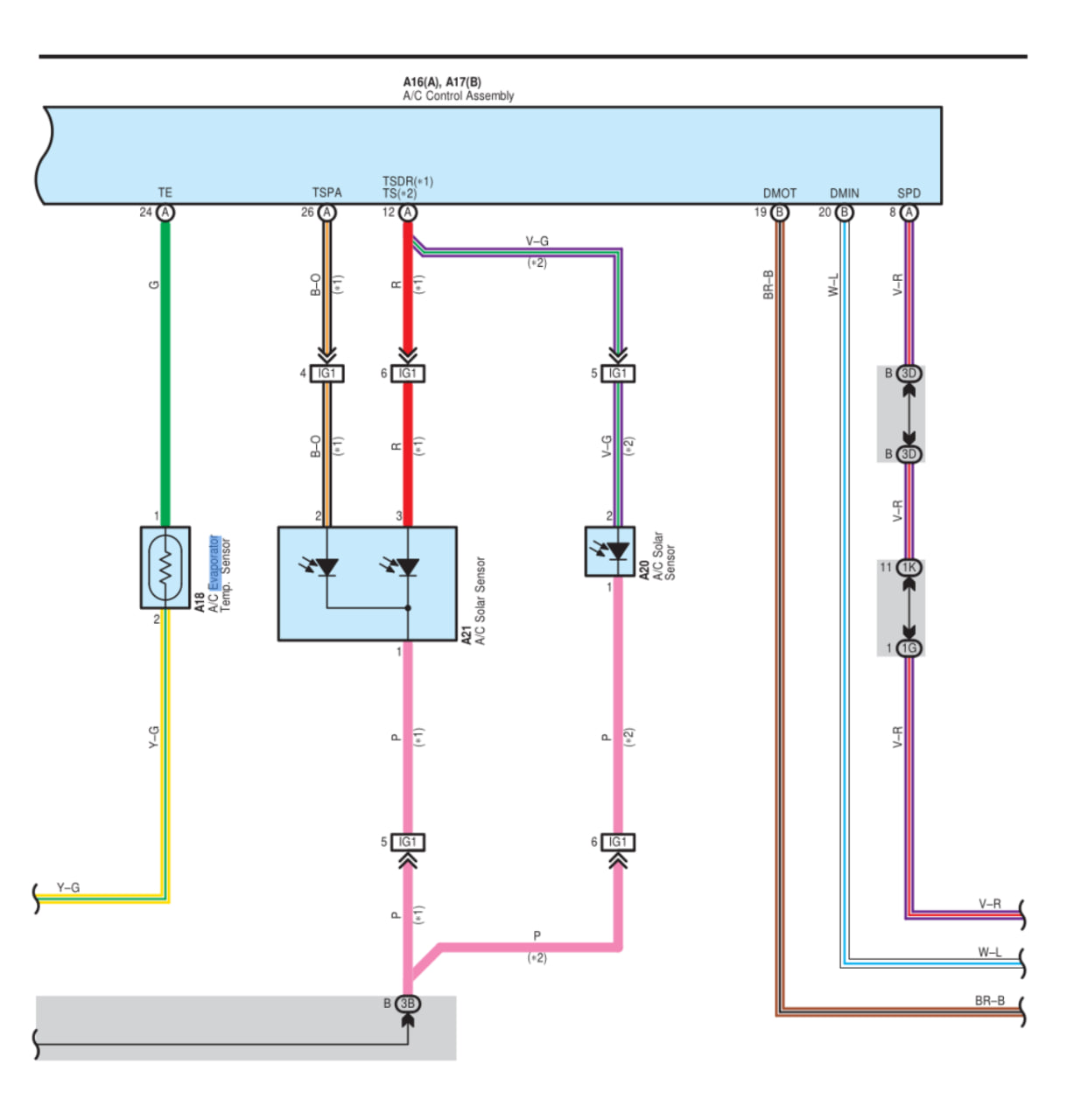
- Which side of the thermistor do I wire the resistor to? (pretty sure it doesn't matter)
This apparently needs to be on the SIGNAL side which according to this diagram would be the GREEN wire. 80% sure on this, would love confirmation.