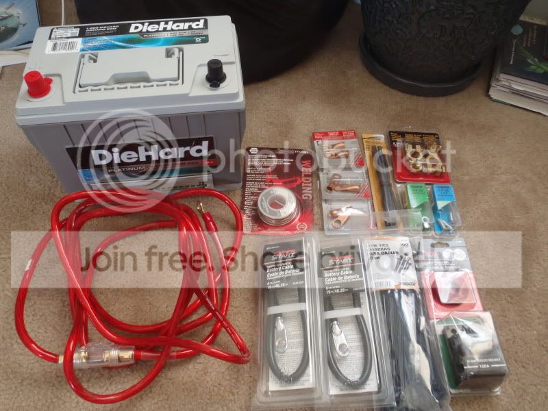
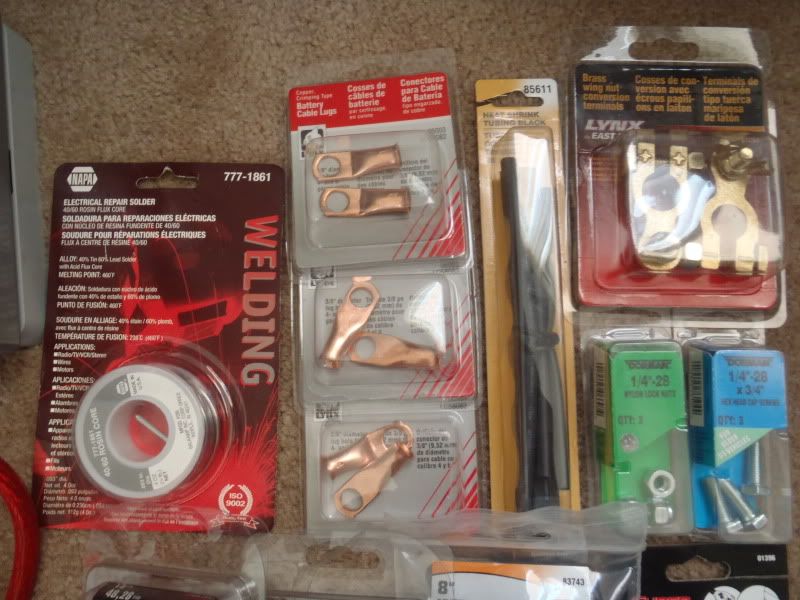
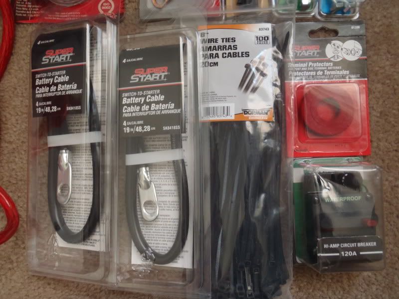
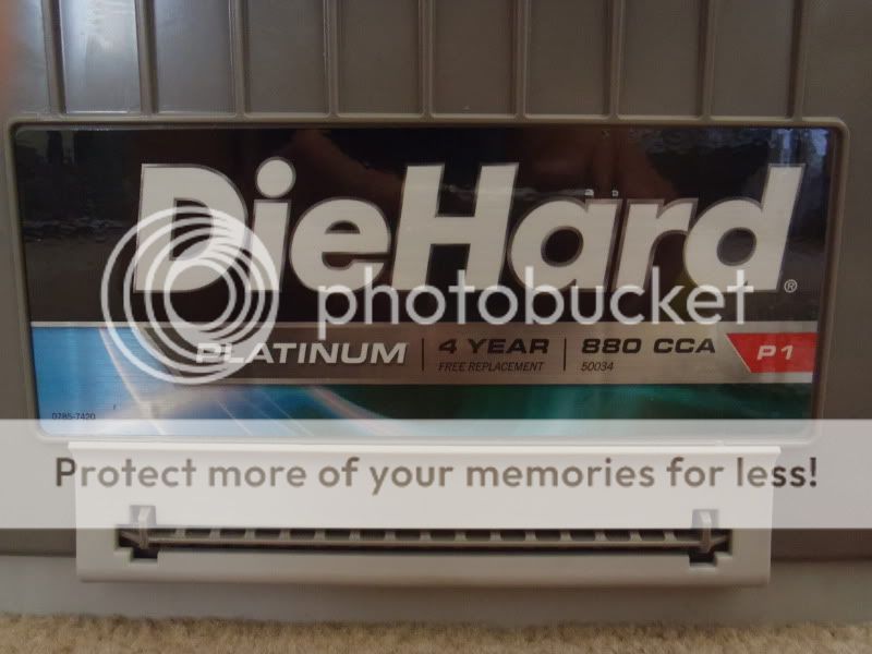
I spent a few afternoons last week finishing up the Big 3 upgrade and getting the battery installed. Everything went pretty smoothly.
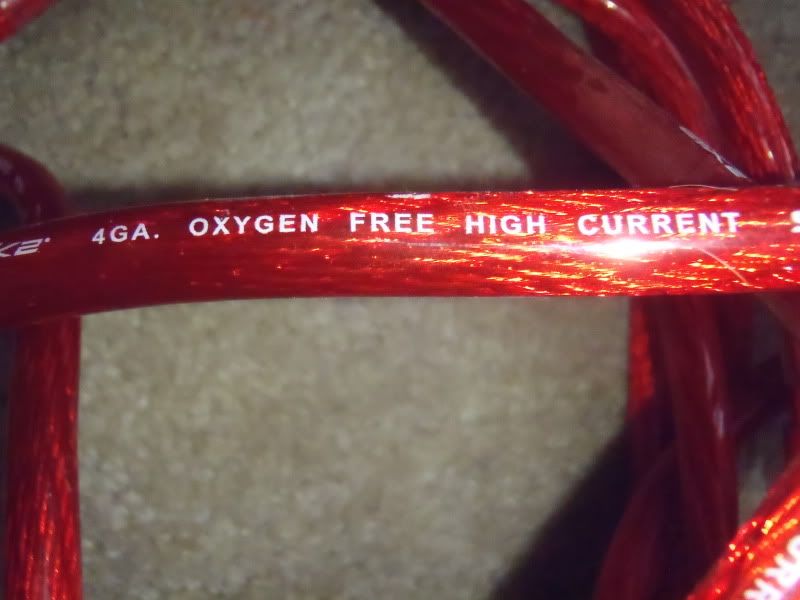
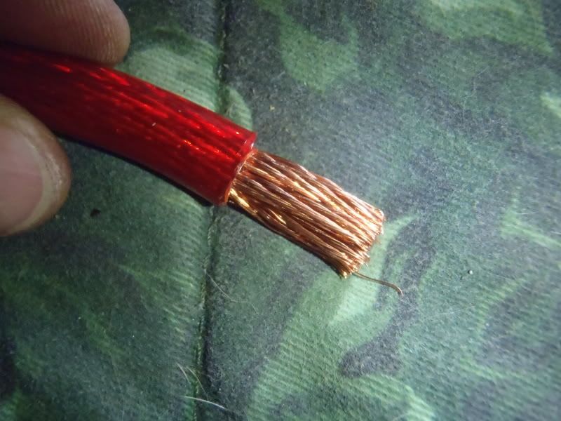
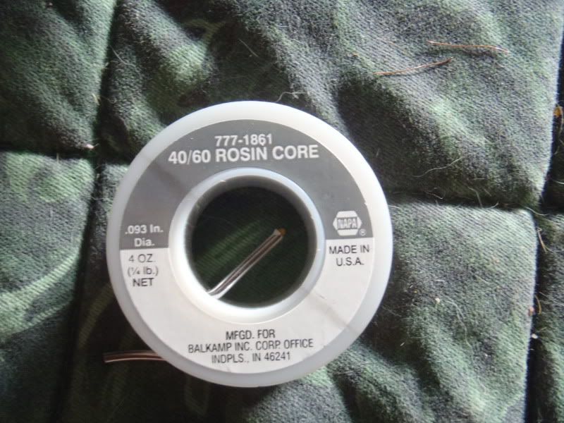
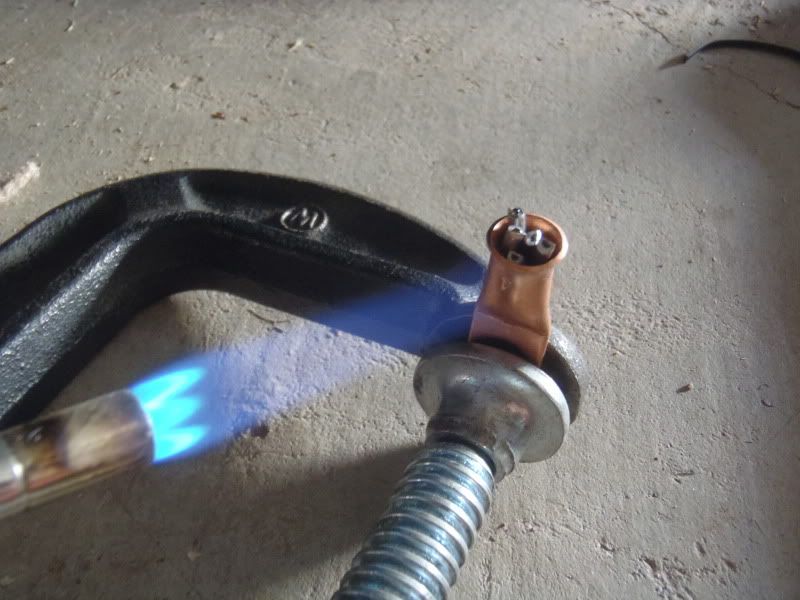
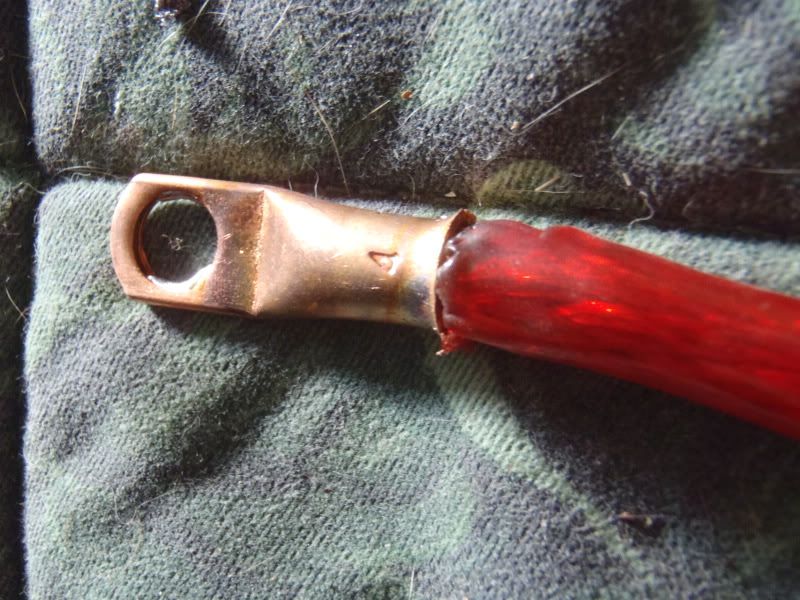
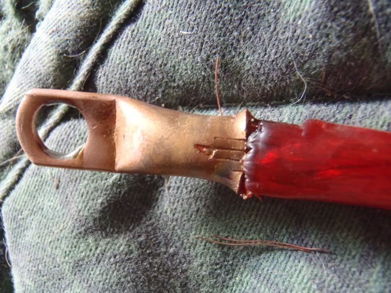
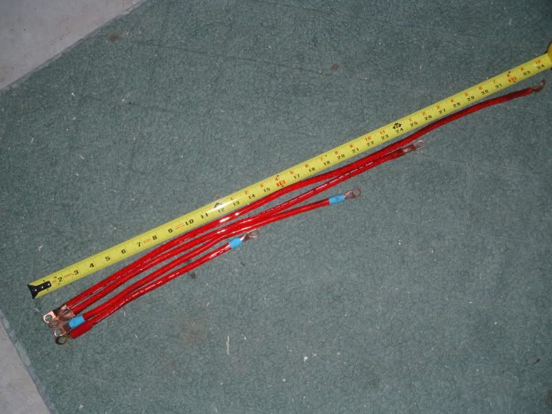
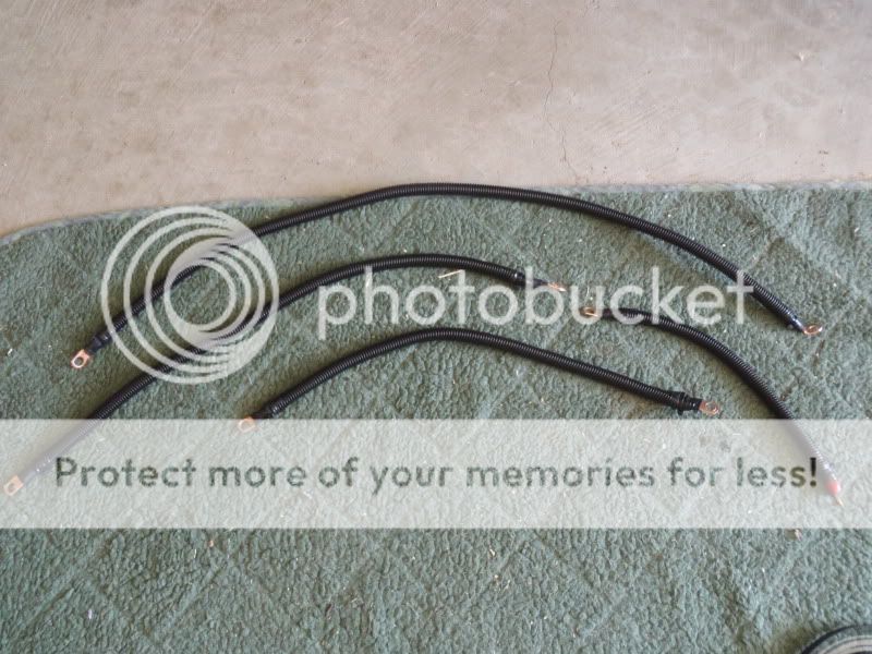
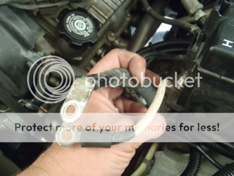
After I got the wires cut to length, and terminals soldered on and crimped, I took the time to add some extra insulation and protection against abrasion. Shorts on these wires = fires, and I don’t like fires in my engine bay.
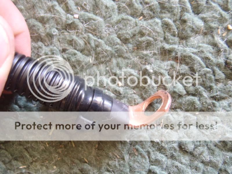
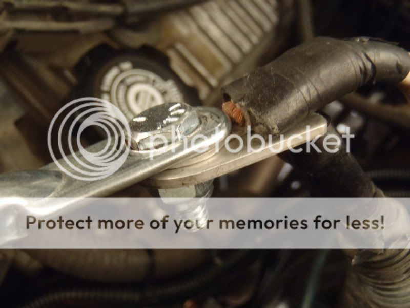
This is a close up of the engine side of the new engine to chassis ground. I had to bend the end of the terminal to accommodate the mounting location on the alternator bracket. You can also see the insulation… heat shrink tubing from wire to terminal, wiring loom over that, electrical tape over that, and then a zip tie around the electrical tape to prevent it from un-wrapping due to the heat in the engine bay.
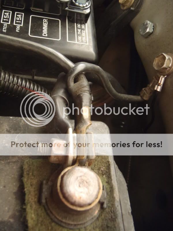
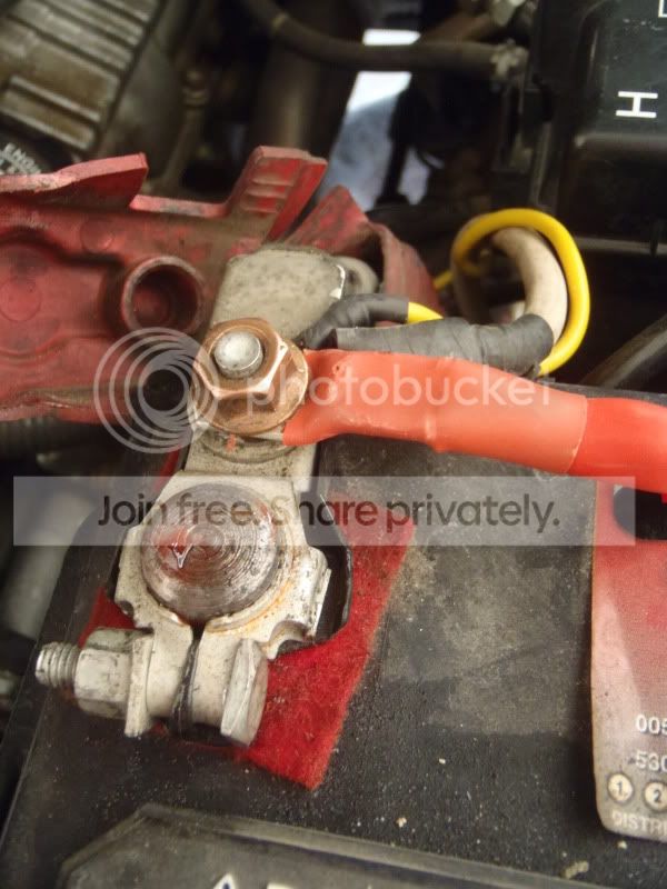
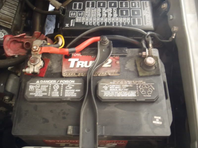
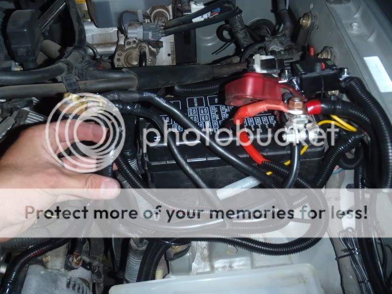
Time to get down to business, but beforehand I took a few shots of the existing setup…
WEAK, weak, WEAK battery to chassis ground… this is probably the weakest link of the stock wiring.
Positive terminal… Wires attached are Alternator charge wire > Batt…… Alt > Fuse Box > Fusible Link > Batt…. Winch Positive Terminal > Batt….. and IPF Lighting Positive > Batt.
The whole shebang…. A leaky battery = one of my engine bay pet peeves!
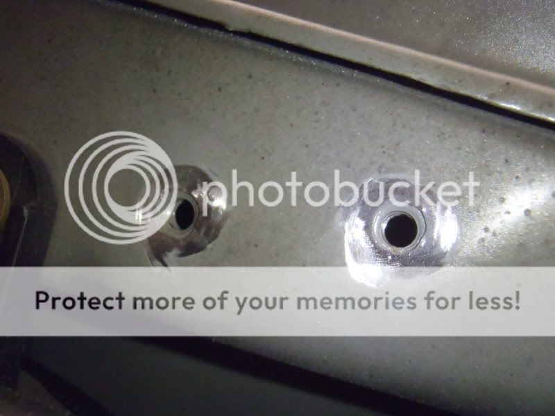
I took the paint off the inner fender @ the ground locations for a better ground connection. I ended up using the stock ground location, and another unused bolt hole located about 2 inches rearward.
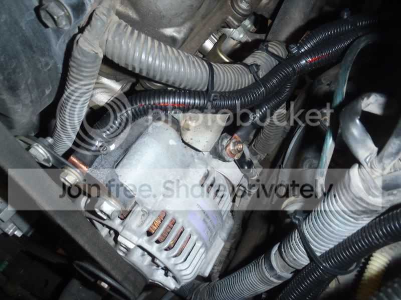
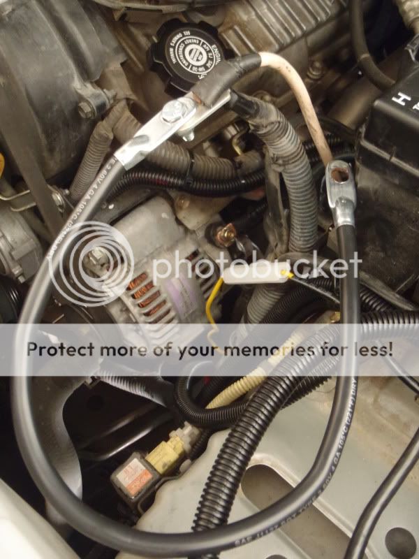
I then hooked up 2 of the Big 3 wires at the alternator side. The Engine to Chassis ground can be connected anywhere on the engine block to anywhere on the chassis. Since the alternator case is the ultimate grounding point of the entire electrical system, I decided to hook up right to the mounting bracket where I would be electrically closest to the alternator case.
The second connection was at the (+) Charging Post on the alternator. You can see the connection to the alternator mounting bracket at left (notice the bent terminal, which I had to do to keep the wiring out of the path of the alternator drive belt), and the connection to the alternator charging post at center…
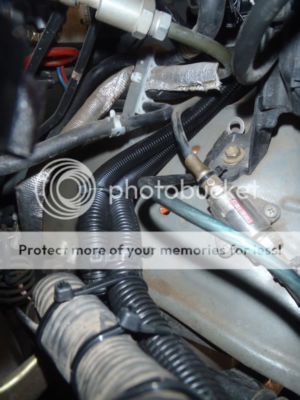
The new wires follow the existing wiring rearward, then separate off toward the driver’s side behind the fuse box….
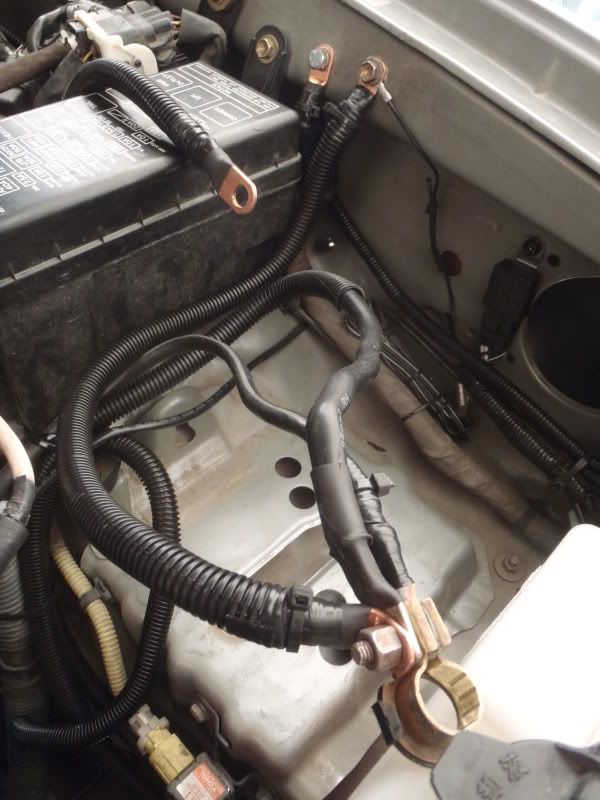
The third wire of the big 3 is the Battery (-) to Chassis wire… I connected one side to the negative terminal and the other side to the stock grounding point on the inner fender. In this shot you can see the Battery (-) to chassis wire in the foreground, the Alternator Case (Engine) to Chassis wire connected to the inner fender just behind it, and the new Alternator Charging Post to Batt (+) wire draped over the fuse box.
Now to deal with extending the stock wiring on the (+) side of things. The two wires that need to be extended are the stock Alternator to Batt (+) wire, and the fusible link coming from the fuse box. The simplest way to do this is like so:
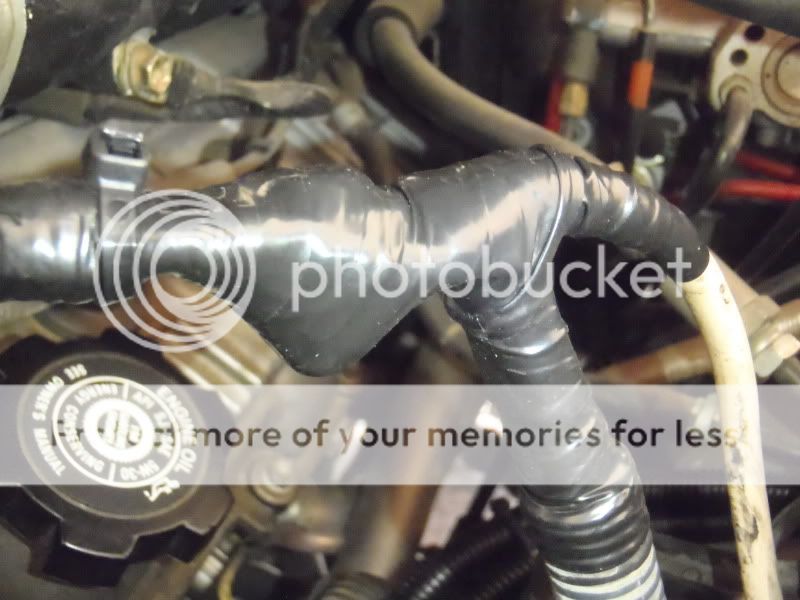
The extension wire is 19 inches long, 4gauge and should have plenty of current carrying capacity to serve as a jumper from the existing wires to the Battery (+) terminal. The bolt and lock nut make sure that there is a strong connection that won’t come loose over time. Finally, I made sure to insulate the hell out of it. I took the entire junction and wrapped it in high quality electrical tape, wrapped that in thick plastic sheet, wrapped with more electrical tape, and repeated one more time. Adding the plastic sheet makes sure the bolt won’t eventually wear through the electrical tape and ground out… again, NO FIRES!
I then had enough length on all the (+) cables to make the connection to the terminal and prepare to drop in the battery.
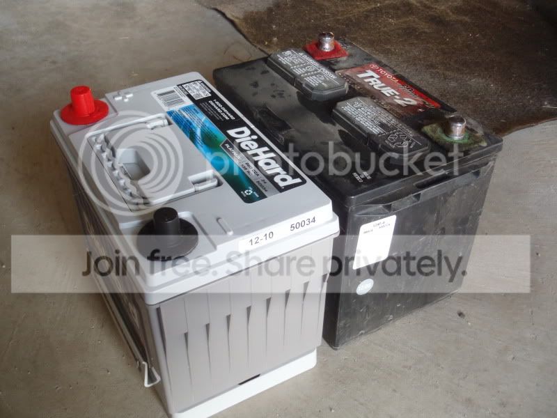
New VS. Old… Again, with the spacer, you can see that the group 34 battery is nearly identical in size to the group 24….(Also, note the reversed terminals)
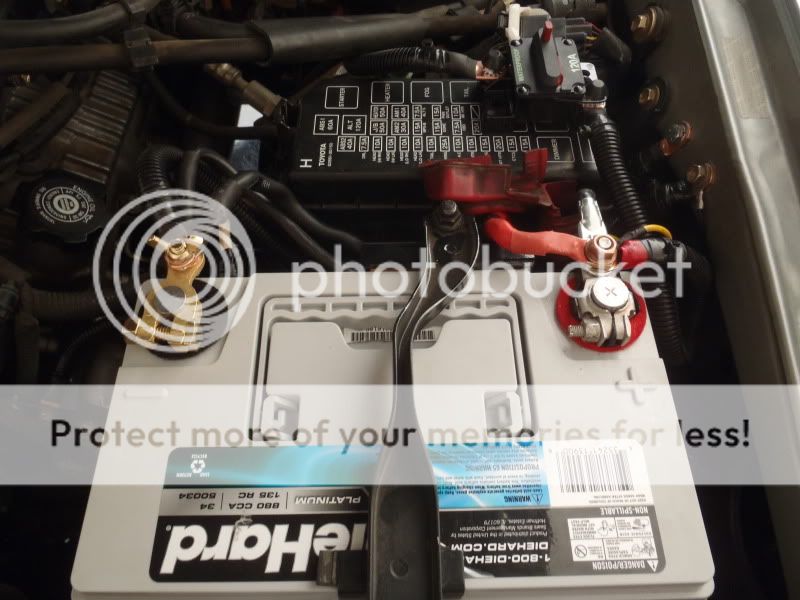
I ended up hacking off the old (-) battery terminal, soldering on a new copper ring terminal, and using a completely new brass battery terminal on the negative side. I felt it was much cleaner, stronger, and provided a better connection than the stock (-) terminal, which is very flimsy.
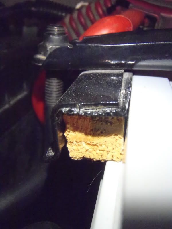
The only thing you have to do to get the stock battery hold down to work on the Die Hard group 34 is cut a small piece of wood, about 3 inches long, by 5/8” square to fill a small gap that is created between the tie down and the rear side of the battery.
Finally, the overall shot of the finished product. You can also see the new 120A circuit breaker I added inline on the new Alternator Charging Post to Battery (+) wire. I used Velcro tape to mount the breaker to the top of the fuse box cover, where it can be easily accessed in case it trips, or for troubleshooting.
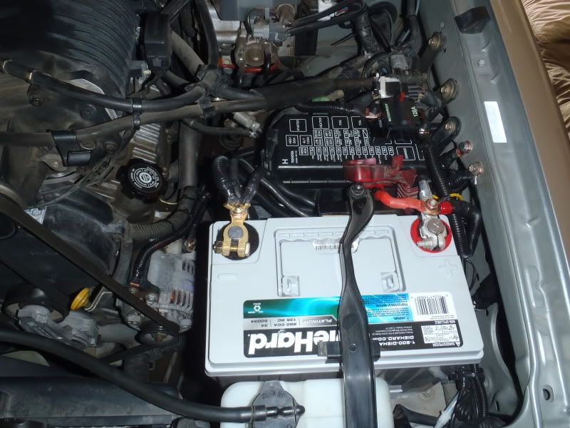
Overall, it was a pretty clean install using the group 34. I have noticed a dramatic increase in idle voltage, which came up from 11.8V to 13.3V. It seems to have smoothed out the idle a little bit, and has definitely been noticeable at night, where the lighting remains at a constant brightness. Before the upgrade, my lighting would dim SIGNIFICANTLY at stoplights or when the truck was idling. I tested the winch on the upgraded electrical system, and it is MUCH HAPPIER. On the old setup, when I activated the winch, the dash lights would flicker a bit and the alternator warning light (red battery symbol) would come on. The Scangauge showed the voltage dropping to almost 11V when the winch was on with the old setup, and with the new setup it does not go below 12.5V. Also, the truck starts much easier with all those cranking amps. For $300, I am VERY happy with this upgrade.