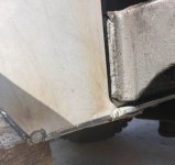
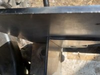
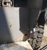
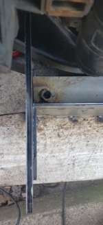
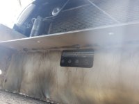
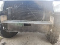
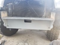
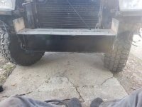
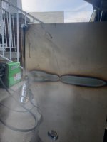
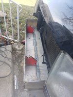
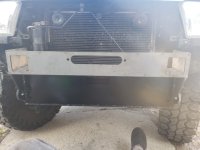
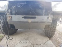
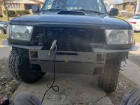
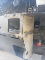
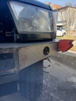
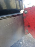
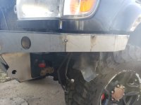
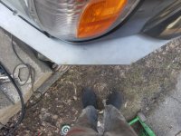
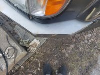
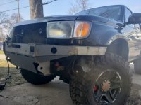
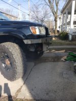
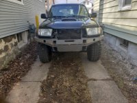
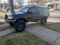
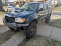
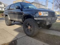
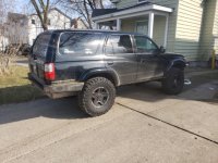
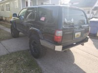
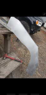
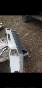
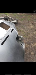
Coastal Offroad High Clearance Front Bumper DIY Writeup

VernySanders

New member
For some insight on how easy it is to assemble these bumpers;

This is my second welding project. Ever..​

The first project was the rear bumper, pictures will be included at the end of that one. Since it was my first project, I didn't document it. Anyhow;

Now that I have about 10 hours of fab experience and a couple hours behind the trigger of a welder I'm comfortable enough to post a D.I.Y. step by step thread on welding one of these bumpers together and what the process is like. (That's how easy it is.)


To be clear this is a High Clearance Front Bumper Kit made by Coastal Offroad and assembled by the consumer.

The equipment i'm using to weld this together is as follows:
  • Titanium 120v Flux Core Welder
  • Vulcan Brand Flux Core Wire .035
  • Electric Grinder
  • Flap Wheel
  • Cut Off Disc
  • Grind Disc
  • Welding Gloves
  • Welding Mask
  • Dremel (Comes in handy for precision alignment)
  • Wire Cutters

This welder cost me $160 from my local Harbor Freight. This is honestly one of the best tools I now own, and I have had zero issues with it. 3/16 is the max gauge recommended to weld with this unit and that is the thickness of these Coastal bumpers. So if you're new to welding, and looking for a cheap and reliable unit I would recommend.

You will also need two 1⁄2-13 x 4.5” OR M12-1.50x110mm Grade 8.8 bolts, nuts, and washers. The Coastal instructions say to purchase extra washers from your hardware store to place on the top and bottom of the frame rail to give wiggle room for re-installation.
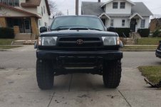
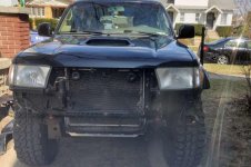
1.jpg

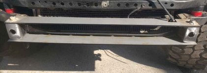
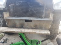
Step One: Remove Front Bumper.

2.jpg

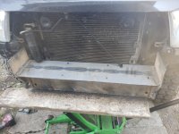
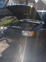
Mine already made my truck look like it was part crack head anyways (as you can surely see). I decided also to remove my front grille because I didn't want to be bothered with any obstruction once I got started. I finished this in three and a half hours from start to finish, not including any finish welding. It was my first time doing this bumper, and all I had to go off of was a well documented video on youtube.

This video. shoutout to Jared Foruria.​

I believe in giving credit where its due. I also believe on sharing experiences like he did so that others don't need to make the same mistakes. The instructions are lacking to say the least. However, for an actual fabricator i'm sure all they would look at is the picture in the plan anyways. So not dissing Coastal at all. Although, it would be worth the time for that organization to buy a quality camera and film their own installation / assembly videos in a high quality, well thought out format, this would almost surely help drive sales as well. (but that's my inner entrepreneur speaking) Lets get back to 4Runner stuff.
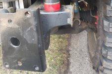
3.jpg

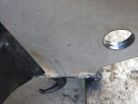
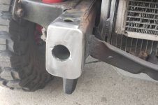
Step Two: Trim your frame rail ends. This isn't a surprise as almost all aftermarket bumpers require the customer to do this.


Simple, prepare angle grinder with cut off wheel, follow up with a flap wheel to make it all nice and smooth. It will look like this:
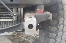
4.jpg 5.jpg


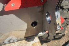
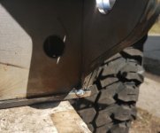
Step Three: Attach piece one on the bottom of the frame rails with the OEM bolts, keeping the factory tow hook, ditching the angle brackets.

You will use piece one as a template to drill a 1/2" hole into the frame for your two grade 8 bolts to slide through.


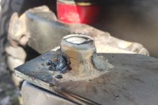
Step Four: Place piece two on the top of the frame, lightly thread your grade 8 bolts into your grade 8 nuts. Weld the nuts into place onto piece two. (Pictured Below)
7.jpg

This is helpful to keep the nuts from moving, kind of. However, this is more important to keep that nut from warping and risking a possible cross threading situation upon installation of bumper.​

It will look like this:

6.jpg

It was quite funny, I go to Ace Hardware, grab the necessities, and drive home. I place said nuts on top of piece two and realize they're nylon lock nuts... Just in case you were wondering why the close up picture of that welded nut looks mutilated. Its just melted nylon. Smelled fantastic!

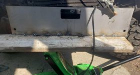
Step Five: Tack weld piece three, mated at a 90 degree angle with piece two.

As you can see in the picture below, I used 11 tacks for this plate. I also shored it up with a floor jack and a piece of wood that spanned the entire underside of the bumper. In doing this I placed ample pressure on piece number 1 preventing it from warping.
8.jpg


Attachments

  • 1.jpg
    1.jpg
    120 KB · Views: 5,063
  • 2.jpg
    2.jpg
    86.7 KB · Views: 4,909
  • 3.jpg
    3.jpg
    120.3 KB · Views: 4,696
  • 4.jpg
    4.jpg
    110.3 KB · Views: 4,693
  • 5.jpg
    5.jpg
    117.1 KB · Views: 4,709
  • 6.jpg
    6.jpg
    111.7 KB · Views: 4,620
  • 7.jpg
    7.jpg
    97.4 KB · Views: 4,598
  • 8.jpg
    8.jpg
    87 KB · Views: 4,503
Last edited:
Register to hide this ad

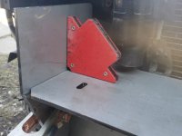
Step Six: Tack weld piece 5 (x2) to piece 4 (x2) Then, Tack at a 90 degree angle with piece 3.

x2 denotes that there are two identical pieces one for each side of the bumper.
Piece one will have a ledge, piece 3 will sit on the front of this ledge, the newly formed piece from 4 and 5 tacked together will sit on the left and right side of this ledge.
Everything will line up PERFECTLY if you're taking the time to ensure precision and craftsmanship.

9.jpg

This picture illustrates the new piece created from 4 and 5 tacked together.
IMPORTANT NOTE TO PREVENT RE-WORK: Tack these parallel with the D-Ring shackle mount hole as shown.
I tacked these in a position above this, and later I had to grind down that tack to fit piece 19. Then tack on the back and you'll be fine.

10.jpg

This picture illustrates a perfect 90 degree angle.
The new piece created by 4 and 5 sits on top of piece 1 at the left and right side with piece 3 sandwiched in the middle.
This picture also illustrates a tack I had to grind down to get the fitment right. So don't tack there.

11.jpg

This is what it will look like all tacked in.

12.jpg

Side profile

13.jpg

Top profile

14.jpg

Zoomed out. NOTE: See that top tack on pieces 4 and 5? Yeah don't tack there.

16.jpg

Top other side

17.jpg

90 degree angle on other side.


Attachments

  • 9.jpg
    9.jpg
    70.9 KB · Views: 4,489
  • 10.jpg
    10.jpg
    26.8 KB · Views: 4,457
  • 11.jpg
    11.jpg
    66.3 KB · Views: 4,572
  • 12.jpg
    12.jpg
    90.7 KB · Views: 4,507
  • 13.jpg
    13.jpg
    51.3 KB · Views: 4,426
  • 14.jpg
    14.jpg
    89.4 KB · Views: 4,502
  • 16.jpg
    16.jpg
    53.6 KB · Views: 4,428
  • 17.jpg
    17.jpg
    63.6 KB · Views: 4,427
Last edited:
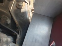

The last post took so many images to properly illustrate the importance of making sure everything fits perfectly.

Being the center of the bumper, its critical to align these pieces to prevent any sort of warped look as an end result. (In my opinion).

Step Seven: Notch and fit piece six. This is your winch plate.

18.jpg

For a pre-cut steel kit that's only been engineered once meaning no more R&D for this design, the least Coastal could do is pre-cut this piece.
I'm assuming Tacoma's don't share this hard line, so this wouldn't require modification on a Tacoma?
Anyhow, for someone like me that has OCD, I expect when I pay $512 USD plus shipping for a weld together kit for a 3rd gen 4Runner I expect it to be fitted for such an application.
Not to need to make my own notches to account for OEM equiptment.
Anyhow.

19.jpg

You can see here that piece 6 sits on top of piece 3 and lines up precisely with the piece 5. Instructions are very clear TO ENSURE THE TRIMMED EDGES FACE THE FRONT OF THE VEHICLE.

20.jpg

Showing 90 degree angle.

23.jpg

Showing the back of the bumper and the alignment.

25.jpg

Piece 6 tacked into place.


Attachments

  • 18.jpg
    18.jpg
    94 KB · Views: 4,405
  • 19.jpg
    19.jpg
    28.3 KB · Views: 4,393
  • 20.jpg
    20.jpg
    55.2 KB · Views: 4,348
  • 23.jpg
    23.jpg
    93.1 KB · Views: 4,398
  • 25.jpg
    25.jpg
    118.3 KB · Views: 4,422
Last edited:
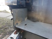


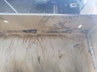
Step Eight: Finish weld the the inside of the bumper that will be inaccessible after welding on piece 19.

NOTE: It's important to mention, up till this point I have not let any of the weight off of the jack. The bumper is still being held extremely tightly into place ensuring no warpage.

27.jpg

28.jpg

29.jpg

Your best bet is to weld about 4 inches at a time, and wait for heat to dissipate about 3 to 5 minutes and pick an area on the other side of the bumper and weld about another 4 inches.

This will minimize warpage.

30.jpg

31.jpg

Step Eight: Prime and Paint the area you just finish welded, and prime and paint the back of piece 19.

As simple as one

32.jpg

two

33.jpg

three

36.jpg

and done!

MAKE SURE YOU SATURATE YOUR WELDS WITH PRIMER ENSURING FULL PENETRATION IN ALL THE LITTLE SPACES.
I used Rusto prime and black spray paint. Not weldable but I already welded everything prior so I really could care less.


Attachments

  • 27.jpg
    27.jpg
    78 KB · Views: 4,427
  • 28.jpg
    28.jpg
    86.2 KB · Views: 4,452
  • 29.jpg
    29.jpg
    63.9 KB · Views: 4,369
  • 30.jpg
    30.jpg
    51 KB · Views: 4,352
  • 31.jpg
    31.jpg
    91.3 KB · Views: 4,480
  • 32.jpg
    32.jpg
    64.7 KB · Views: 4,439
  • 33.jpg
    33.jpg
    69.8 KB · Views: 4,621
  • 36.jpg
    36.jpg
    83 KB · Views: 4,509
Last edited:
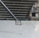
Step Nine: Tack in Piece 7 while you wait for your paint to dry.

37.jpg

You can see this is where my first and only warpage mistake occurred towards the top of this piece. This happened because I did a complete weld on top of the winch plate (piece six).
So as long as you leave the top of that place only tacked into place, you shouldn't run into this mis-alignment. Luckily for me this isn't noticeable on the finished product.

38.jpg

39.jpg

Step Ten: Tack in piece 19 below piece 7.

40.jpg

CONGRATULATIONS: This completes the center of the bumper.


Step Eleven: Tack piece 8 and piece 16.

The difference between the two is piece 16 is pre-cut for the OEM component that would otherwise be in the way. ( Thank you Coastal Offroad )
Below you can see piece 16 is on the passenger side of the truck.
Kind of hard to mix that up honestly.

41.jpg

By placing three tacks on the front and one on the rear of the bumper, pieces 8 and 16 stayed extremely firm for the rest of this assembly process.
It is important to note, if you align these two pieces properly with with the rest of the bumper ( the body lines are easy to see )
You should already be at your half inch spec allowing for body roll due to the engineering of the bumper.

42.jpg

Here you can see the three tacks in the front and the one in the rear.
By tacking in these pieces this way, they become stout enough to maintain the half inch body line by themselves without you holding them into place.

Step Twelve: Tack in both piece 9's.


43.jpg

Before tacking on piece nine, its essential to create a 45 degree angle with a grinding wheel on the backside of where it connects to piece 7
to create a perfect and sharp design structure with your bumper.
This is another thing Coastal should look into doing into the future,
in order make this as simple as possible for people to do, especially beginners and advertise it to increase sales.

If I were to come out with a competitive product line, ( im not going to LOL ) I would do it. Small details make all the difference in products like these.

44.jpg

Note: When you create the 45 degree angle on piece nine it allows you to maintain a perfect structural design.


Attachments

  • 37.jpg
    37.jpg
    72.4 KB · Views: 4,329
  • 38.jpg
    38.jpg
    116.7 KB · Views: 4,349
  • 39.jpg
    39.jpg
    124.1 KB · Views: 4,432
  • 40.jpg
    40.jpg
    106.8 KB · Views: 4,569
  • 41.jpg
    41.jpg
    77.8 KB · Views: 4,663
  • 42.jpg
    42.jpg
    88 KB · Views: 4,329
  • 43.jpg
    43.jpg
    52.6 KB · Views: 4,456
  • 44.jpg
    44.jpg
    82.2 KB · Views: 4,303
Last edited:
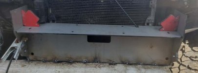

45.jpg

46.jpg

47.jpg

48.jpg

49.jpg

50.jpg

I'll include the rest of the instructions shortly.


Attachments

  • 45.jpg
    45.jpg
    60.2 KB · Views: 4,550
  • 46.jpg
    46.jpg
    100.7 KB · Views: 4,317
  • 47.jpg
    47.jpg
    101 KB · Views: 4,327
  • 48.jpg
    48.jpg
    71.2 KB · Views: 4,586
  • 49.jpg
    49.jpg
    118.3 KB · Views: 4,409
  • 50.jpg
    50.jpg
    102.1 KB · Views: 4,348
Last edited:


52.jpg

53.jpg

54.jpg

55.jpg

56.jpg

58.jpg


Attachments

  • 52.jpg
    52.jpg
    116.7 KB · Views: 4,438
  • 53.jpg
    53.jpg
    101.9 KB · Views: 4,383
  • 54.jpg
    54.jpg
    93 KB · Views: 4,282
  • 55.jpg
    55.jpg
    108 KB · Views: 4,343
  • 56.jpg
    56.jpg
    81.3 KB · Views: 4,271
  • 58.jpg
    58.jpg
    108.7 KB · Views: 4,275
Last edited:

looks good

I was thinking of buying one of these...until I read it is DIY. But now seeing this, it doesnt seem so bad. Might have to look more into this.
 
I was thinking of buying one of these...until I read it is DIY. But now seeing this, it doesnt seem so bad. Might have to look more into this.

I wanted these bumpers because of the clearance and how compact they are, yet effective and powerful, compared to something like an ARB bumper which may be powerful but is not effective at all.

My initial plan was to tack it together and take it to a fab shop and have a professional welder do the actual welding but then I got really comfortable behind the mask and decided to do it all myself. If you're looking to push yourself to learn a new skill, this is the best project honestly. The way its engineered makes it insanely easy to put together and since its DIY you get to customize the look as you go.
 
Last edited:

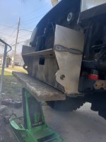
I got a couple hours to work on it today (weather finally permitted)
 

Attachments

  • Screenshot_20200330-180806_Gallery.jpg
    Screenshot_20200330-180806_Gallery.jpg
    138.2 KB · Views: 4,226
  • Screenshot_20200330-180755_Gallery.jpg
    Screenshot_20200330-180755_Gallery.jpg
    138.7 KB · Views: 4,244
  • Screenshot_20200330-180739_Gallery.jpg
    Screenshot_20200330-180739_Gallery.jpg
    136.9 KB · Views: 4,151
20200405_162820 (1).jpg
I will be finishing this thread and posting all information on how I painted it etc.
 

Attachments

  • 20200405_162820 (1).jpg
    20200405_162820 (1).jpg
    89.3 KB · Views: 4,260
I think I'm going to go this route. I got a quote to do it for me for $350 or I can do it myself and buy the tools for that price. Decisions decisions. Hmmmmmm.....
 
Hey, nice work! I actually just bought one of these little welders too. What settings did you find worked best for welding that 3/16" plate? I realize that's at the upper limit of the welder's capability.
 
Great write up, almost ready to assemble the one I've had for a year.

Sent from my Pixel 3 XL using Tapatalk
 
Kudos for taking this on as a first/early welding project.

You should probably leave a lot more clearance between the AC line and the winch plate - the body moves something like 3/8" compared to the frame and so you need plenty of clearance there.

-Charlie
 
Hey, nice work! I actually just bought one of these little welders too. What settings did you find worked best for welding that 3/16" plate? I realize that's at the upper limit of the welder's capability.

Well the wire speed depends on how fat you want the welds, on the shackles mounts I actually dropped my wire speed so I could focus on my figure 8 pattern weld. I was operating at 7 on wire speed and the second highest power setting. For an average weld I would have wire speed at 9 and still second highest power setting. I dont think I ever used the max power setting. I also used the .35 wire I noticed that makes a big difference over the .30 on this machine while trying to weld at the highest capability
 
Well the wire speed depends on how fat you want the welds, on the shackles mounts I actually dropped my wire speed so I could focus on my figure 8 pattern weld. I was operating at 7 on wire speed and the second highest power setting. For an average weld I would have wire speed at 9 and still second highest power setting. I dont think I ever used the max power setting. I also used the .35 wire I noticed that makes a big difference over the .30 on this machine while trying to weld at the highest capability

So you found that the 0.035 wire helped you with welding thicker material?
 

Members online

Forum statistics

Threads
278,315
Messages
3,554,102
Members
248,016
Latest member
Advally Service

Trending content

Back
Top