
DIY Big 3 Wiring Upgrade Kit

4Running Daily

New member
So I recently replaced my battery and I figured I would do the Big 3 upgrade while I was at it. Sadly, living in a dorm room, I couldn't build the wires myself because I have no tools. Luckily there is a man on Tacoma World that builds kits for 1st gen Tacoma's. So in this thread I will be posting photos of the kit and my install of it.

Information of kit:
Stage 1 consists of new positive and negative battery cables and terminals for an Optima, or heavy duty top-post battery. Stage 1 uses 2-gauge welding cable for the power cable to the starter, as well as the ground cable to the engine block. It also uses 4-gauge welding cable for the alternator, as well as the cable to the fuse block. All cables have soldered terminal ends, which are better than the factory crimp connections. The only ends that do not have soldered terminals are the ends that go to the heavy-duty battery terminals, which use a brass allen set-screw. These set-screw ends are quite common in the audio industry for battery terminals.

Link to kit:
1st Gen (and upcoming 2nd Gen) electrical system upgrade! - Tacoma World Forums

Cost of materials to do it yourself roughly are around $75.
The kit itself was $110.

Here are the pictures:
IMG_3572 by 4Running Daily, on Flickr
IMG_3574 by 4Running Daily, on Flickr
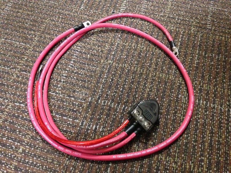
IMG_3575 by 4Running Daily, on Flickr
IMG_3576 by 4Running Daily, on Flickr
IMG_3578 by 4Running Daily, on Flickr
IMG_3579 by 4Running Daily, on Flickr
 
Last edited:
Register to hide this ad
Whats the difference between using those cables as opposed to standard power cables? I have like 20ft of 2ga cables that I was going to use for this project already but waiting to upgrade battery.
 
I looked at doing this recently when upgrading my battery, but there is a serious safety issue with it. See the posts I made here for details.

http://www.toyota-4runner.org/3rd-g...ring-ugrade-3rd-gen-toyota-4runner-how-5.html

You should only do the 'big 2' - don't upgrade the alternator wiring unless you remove the fused link between the battery and the fuse box. Otherwise you have a 240 amp fused circuit instead of a 120 amp fused circuit and your truck will probably burn to the ground before those fuses ever blow.
 
I looked at doing this recently when upgrading my battery, but there is a serious safety issue with it. See the posts I made here for details.

http://www.toyota-4runner.org/3rd-g...ring-ugrade-3rd-gen-toyota-4runner-how-5.html

You should only do the 'big 2' - don't upgrade the alternator wiring unless you remove the fused link between the battery and the fuse box. Otherwise you have a 240 amp fused circuit instead of a 120 amp fused circuit and your truck will probably burn to the ground before those fuses ever blow.

You're fine to upgrade the alternator wiring, just run it straight to the battery and not the fuse box.

Keep the small wire in there to go to the fuse box, and run the other wire straight to the pos terminal.

That's what I did, and it works just fine.
 
You're fine to upgrade the alternator wiring, just run it straight to the battery and not the fuse box.

Keep the small wire in there to go to the fuse box, and run the other wire straight to the pos terminal.

That's what I did, and it works just fine.

It may work just fine but it still will take 240 amps to blow either fuse, when the Toyota engineers designed the wiring system to be fused at 120 amps. It will always work just fine until something shorts out and the fuses don't blow (but the wiring burns and the truck follows). Fuses are there to protect the wiring, components, truck, and you (and your passengers) when something goes wrong.

If you remove the wire from the fuse box to the alternator (wire #3 in the 'big 3' diagram), so you only have one current path to the alternator, through the new wire (leaving the fused link to provide power to the rest of the circuits) that would be okay. But if you leave the wire from the fuse box to the alternator, you have 2 current paths to the fuse box, with a total fused capacity of 240 amps.
 
Last edited:
I was hoping them to be in the 4runner. Can't wait to see them.

One guy in the apartment building I lived in as a freshman in college brought with him a Lincoln welder and plasma cutter. He uncle stills owns a transmission chain in Virginia. We blew the circuits constantly with him showing me how to weld in the basement.
 
It may work just fine but it still will take 240 amps to blow either fuse, when the Toyota engineers designed the wiring system to be fused at 120 amps. It will always work just fine until something shorts out and the fuses don't blow (but the wiring burns and the truck follows). Fuses are there to protect the wiring, components, truck, and you (and your passengers) when something goes wrong.

If you remove the wire from the fuse box to the alternator (wire #3 in the 'big 3' diagram), so you only have one current path to the alternator, through the new wire (leaving the fused link to provide power to the rest of the circuits) that would be okay. But if you leave the wire from the fuse box to the alternator, you have 2 current paths to the fuse box, with a total fused capacity of 240 amps.


You didn't read what I said.

I said, I have the STOCK wiring to the Fuse Box.

The UPGRADED wire from the alternator goes STRAIGHT to the (+) of the battery. Does NOT go into the fuse box.


The reason for upgrading the wire FROM the alternator is to allow more current into the battery. I didn't upgrade that wire, I added another straight to the battery.
 
You didn't read what I said.

I said, I have the STOCK wiring to the Fuse Box.

The UPGRADED wire from the alternator goes STRAIGHT to the (+) of the battery. Does NOT go into the fuse box.


The reason for upgrading the wire FROM the alternator is to allow more current into the battery. I didn't upgrade that wire, I added another straight to the battery.

But that is my point. If you did not disconnect the existing wire from the alternator to the fuse box (wire #3 in the big 3 diagram) you now have 2 current paths between the battery and the alternator/fuse box, with a total fused capacity of 240 amps. You did not replace the existing wire from the alternator to the battery (via the fuse box) you added a second one in parallel with it (and I hope by 'straight to the battery' you mean with a 120 amp fuse or circuit breaker in line with it), which doubled the fuse capacity. If you are going to run both wires like that, you should change both fuses from 120 amp fuses to 60 amp fuses, but you can't do that since other things are powered via the 120 amp fuse in the fuse box.

In this diagram, wires #8 (new wire) and #3 (existing wire to the alternator from the battery, via the fuse box) are in parallel, which is the problem.

2_zpsbfc05fb7.png~original


As an aside, I don't think this mod adds any capability or more power availability. The stock alternator is only going to supply 70 (or 80 amps if it is an 01 or 02) no matter what size the wiring is. The factory wiring is certainly large enough to handle that current without any appreciable voltage drop (it is a very short run - voltage drops occur on longer runs - like 20' or more). If you upgrade to a CS144 alternator you should probably change the 120 amp fuse in the fuse box to 150 amp or so, but other than that there is no real need to upgrade the wiring. The wire to the starter is also plenty large enough, unless you have a manual transmission, override the clutch safety switch, and plan to use the starter to pull the truck up a hill. The voltage drop on that wire, at full load on a very cold morning, is probably a couple of tenths of a volt. Adding a heavier ground wire is probably the best upgrade, especially if you have extra lights or radios.

If you are using your winch, it is connected directly to the battery and any current the winch needs beyond the 70 (or 80) amps the alternator can supply is going to come from the battery, so no additional current is going through the wire to (or from) the alternator even when the winch is running.

The best upgrade would be to add a Blue Sea fuse panel and run all the aux wiring through it (lights, HAM radio, etc.) as I did. Run a #4 wire to it and upgrade the ground wire, and you've accomplished more than the big 3, is much easier to do, and more effective at powering your accessories (and won't burn down your truck should you ever get a short in the alternator).

DSC_1717_zps12e7bce2.jpg~original
 
Last edited:
It may work just fine but it still will take 240 amps to blow either fuse, when the Toyota engineers designed the wiring system to be fused at 120 amps. It will always work just fine until something shorts out and the fuses don't blow (but the wiring burns and the truck follows). Fuses are there to protect the wiring, components, truck, and you (and your passengers) when something goes wrong.

If you remove the wire from the fuse box to the alternator (wire #3 in the 'big 3' diagram), so you only have one current path to the alternator, through the new wire (leaving the fused link to provide power to the rest of the circuits) that would be okay. But if you leave the wire from the fuse box to the alternator, you have 2 current paths to the fuse box, with a total fused capacity of 240 amps.

Toyota based the 120A on the capacity of the alternator, and size of wire #3. There isn't any limitation, or minimum on current flow. I still agree with the logic, just not on the urgency to follow your lead.

:couch2:
 
This is Bill, AKA BamaToy1997 on Tacomaworld, as well as vendor here on T4R, AKA Marion Bumper2Bumper. I just wanted to post some comments in here and field any questions others may have.


That's not a bad premium at all, to have somebody else do all the crimping and assembling. Does that $110 include shipping?

The shipping for the Stage 1 Kit is $11, and the Stage 2 Kit shipping is $15.

Whats the difference between using those cables as opposed to standard power cables? I have like 20ft of 2ga cables that I was going to use for this project already but waiting to upgrade battery.

Standard battery cables have a smaller cross section of copper cable. The upgraded welding cables that I use have a much tighter, and large cross section. This increases the current capacity of the cable, as well as reduces the heat in the cable under heavy loads (due to its larger cross section) When it comes to this, a 2 gauge welding cable is capable of the same amount of current that a standard automotive 0 gauge cable is capable of. These cables are also much more flexible, allowing easier and more varied routing.

I looked at doing this recently when upgrading my battery, but there is a serious safety issue with it. See the posts I made here for details.

http://www.toyota-4runner.org/3rd-g...ring-ugrade-3rd-gen-toyota-4runner-how-5.html

You should only do the 'big 2' - don't upgrade the alternator wiring unless you remove the fused link between the battery and the fuse box. Otherwise you have a 240 amp fused circuit instead of a 120 amp fused circuit and your truck will probably burn to the ground before those fuses ever blow.

My system is designed so that the alternator output goes DIRECTLY to the battery, not the fuse box. A smaller gauge cable then goes to the vehicle's fuse box and still uses the factory alternator fuse, thus protecting the vehicle's wiring system. There is no different of a risk of fire, and this is actually a safer way to connect the alternator directly to the battery. This system has been used for a long time without any undue issues.

The Stage 1 Kit, as the OP purchased, is the first step towards the next big step, and that is the high output alternators. We supply 130A, 200A, and 250A alternators for ALL Toyota truck vehicles from 1995 Tacoma, and 3rd gen 4Runners, up to the current model year. Each of these alternators are custom built with rewound stator AND armature, and are built using the original housings so they bolt right into the existing electrical system, and require NO customization, unlike the CS144. AND all of our alternators are built in the US, and come with a 1 year replacement warranty. The Stage 1 Kit is REQUIRED for the higher output alternators in the 1st Gen Tacoma, and like model 4Runner because the factory cables cannot carry the maximum output of the alternator. This works GREAT when you have a winch or high power stereo, and want to maintain steady voltage.

If anyone has any questions feel free to ask!
 
This is Bill, AKA BamaToy1997 on Tacomaworld, as well as vendor here on T4R, AKA Marion Bumper2Bumper. I just wanted to post some comments in here and field any questions others may have.

My system is designed so that the alternator output goes DIRECTLY to the battery, not the fuse box. A smaller gauge cable then goes to the vehicle's fuse box and still uses the factory alternator fuse, thus protecting the vehicle's wiring system. There is no different of a risk of fire, and this is actually a safer way to connect the alternator directly to the battery. This system has been used for a long time without any undue issues.

If anyone has any questions feel free to ask!

So the wire from the alternator the battery does not have a fuse in it? The wire is connected directly from the battery to the alternator? If so, that is potentially a problem. Toyota fused the alternator cable to protect the alternator (primarily) as well as the rest of the circuits. If you happen to connect the jumper cables backwards on a cold night, your alternator will fry instantly since there is no fuse to blow.

It looks like from your instructions you are removing the original cable from the fuse box to the alternator. That is good, and what I have been recommending. That removes the 'dual circuit' paths, and will keep the wire from the battery to the alternator from feeding back into the fuse box downstream of the 120 amp fuse. However, without a fuse in the line from the battery to the alternator, there is nothing to protect the alternator, or the battery if the alternator shorts out.
 
The best upgrade would be to add a Blue Sea fuse panel and run all the aux wiring through it (lights, HAM radio, etc.) as I did. Run a #4 wire to it and upgrade the ground wire, and you've accomplished more than the big 3, is much easier to do, and more effective at powering your accessories (and won't burn down your truck should you ever get a short in the alternator).

This is basically what I did with the exception I also added in a positive dist block inside the fender area. I was going to do the big 3 also but read your comments abut it and it totally makes sense. I have decided NOT do do the big 3.

It's in my thread here:
BSFB Install
 

Members online

Forum statistics

Threads
278,312
Messages
3,554,086
Members
248,016
Latest member
Advally Service

Trending content

Back
Top