Using Oxygen (O2) Concentrator in T4R

Salvo Jimmy

Member
These are used to supply O2 to folks needing it when traveling. They can be supplied by 12v DC.

I have searched and found nothing related. BTW I am a mechanical type with only rudimentary electrical experience. So this might not make sense to some more experienced.

I am attempting to use an Oxlife Independence (at 2.0 LPM) in my 2016 Toyota 4Runner and a 2008 Lexus ES 350. Both have 12v 10 amp rated outlets. The machine per operator manual should both be powered by the vehicle and charge the battery at the same time.

In both vehicles, using the 12v outlet on the dash, closest to the battery, (as recommended by the operator manual), the Oxlife after a few minutes disconnects from the vehicle power and reverts to battery. Sometimes in the Lexus it stays powered by the vehicle but does not charge the battery, and yes the battery needs charging.

Both vehicle electrical systems are working properly per dealer. If the unit is unplugged and replugged after about 30 sec, it will be powered by the vehicle for a short time then revert to battery. And yes the vehicle receptacle has power as indicated by a light and the plug has not come loose. There is no indication on the unit it is using external power and in the case of the Lexus, the indication sometimes indicates external power but there no indication the batt is being charged.

I notice the operator manual recommends a 15 amp circuit vs 10 amp.

My guess is the unit is drawing enough amps to lower the voltage to below 11.5v which will activate an external power disconnect on the machine, as the circuit is rated at 10 vs 15 amps, and the low voltage disconnect on the O2 machine is activated.

I have also tried an Eclipse 5 machine, which will operate like the Oxlife on 12v DC, with similar disconnect results.

The supplier of both the machines of course says it is a vehicle problem.

I am thinking I could possibly install another 12v outlet rated at 15 amps vs 10 amps but neither the dealer or my independent trusted mechanic will do it.

Any thoughts would be appreciated.
 
Register to hide this ad
Sounds like it's not getting enough amp draw, I'd run a 15 amp rated circuit straight to the battery

This!

If you saw the tiny wires on the factory outlets, it's not a surprise you can't get enough juice. I would bet they can pass 5 amps, but probably not more than that with any stability.

Narat
 
Sounds like it's not getting enough amp draw, I'd run a 15 amp rated circuit straight to the battery

My thought as well.

Here is what mfg says

Hi Ted,

You are correct with the amperage draw. We do recommend getting an inverter, if you are using a device at 2.0LPM or higher on continuous or 4.0 or higher on pulse. I hope you can find my recommendations below helpful.


Tip #1:
When the device is connected to DC power try twisting the DC cord in the DC/cigarette outlet. This will scrape the contact point hopefully making a better connection for the device.

Tip #2:
There may be too much of a power draw on the vehicles electrical system (i.e.: air conditioning, radio, GPS system, etc.) Try eliminating some of these draws in order to boost power to the device. The device requires a minimum of 150watts (15amps) to run on all settings and to charge the batteries effectively. The vehicle may only be equipped to provide up to 120watts (12amp). This information can be verified by looking in your user manual for your vehicle. While the device is connected to DC power you can access the “Provider Screen” to see how much voltage the device is actually receiving (instructions on how to access the provider are screen below):

Tip #3:
End Users may need to purchase an inverter. I have also attached information for you about an inverter that our engineering team found that works best with our POC. Please be sure that the power inverter is attached directly to the vehicle battery.

Samlex Power Inverter Complete Kit Requirements

Samlex Power inverter – Model : SAM-450-12
(2) Ring Terminal, 6 AWG, NO.10 screw size, McMaster PN:7113K225
(2) Brass flat washer, NO.6 screw size, .156 ID, .312 OD, McMaster PN: 95395A105
10 ft., 6 AWG, Red, Wire
10 ft., 6 AWG, Black, Wire
Little Fuse Inc. 60 Amp, 30 VDC, PN: 0299060.zxnv
Maxi fuse holder PN: MAHc0001zxj


Please note that this is only a recommendation and is not a requirement to buy. The listed parts above can be purchased on amazon.com (or an automotive service provider) and can be installed by an auto mechanic.

*If you decide to purchase an alternative inverter please be sure the inverter is a minimum of 450watts and connects directly to the vehicle battery. Inverters that connect to the DC/ cigarette outlet may not function properly and may still cause the device to alert for ‘low external power’.


Accessing the Provider/ Dealer Screen:
1) Press and hold the Mode and Down Arrow keys at the same time till a 2nd screen appears (to exit screen press UP Arrow).
2) You are now viewing the Provider/Dealer Screen (please note that dealer screens may vary, however, the basic information below can still be found):
cid:[email protected]

3) Information provided on this screen includes:
I. Serial Number (SN) of unit
II. How long the unit has currently been running.
III. Temperature readings for the battery, motor, and display.
IV. Bay 1 (B1) and Bay 2 (B2) information on the batteries: charging/discharging; battery charge %; expected time left on battery (mins.) **If the batteries are charging, there will be a (-) mA number on the screen, as pictured above; batteries being used will be a (+)mA number. This verifies that the batteries are charging **
V. VIN: Voltage In (You want to be getting at least 12V, ideally 12.5V in the car) (if the voltage reads 11.5 and lower the unit will alert low external power and will revert to batteries for a steady source of power and you may need to purchase an inverter).
VI. Flow and Purity readings

Batteries Not Charging:
If there is no Lightning Bolt reduce the device setting to 0.50 Continuous and wait for the indicator to appear. Increase the setting by 0.5LPM increments to the desired flow rate. If the battery is fully depleted, turn off the device to expedite charge times. (Batteries will not charge on settings higher than 2.0 Continuous or 4.0 Pulse).


Best Regards,

Maryna Pov
O2 Concepts- Technical Support
199 Park Rd Extension
Middlebury, CT 06762
Office:(877) 867-4008 x367
[email protected]
O2 Concepts
 
Installing an inverter is too expensive and too much work.

Try a test first at 12V in the garage or driveway.

Get a 12V socket and connect it directly to the battery and see if the O2 unit continues to work. If it does, then a larger wire and separate socket inside the T4 should fix it. As others stated, run the new wire directly to the battery, use a fuse and mount it in a convenient place.
 
Last edited:
Installing an inverter is too expensive and too much work.

Try a test first at 12V in the garage or driveway.

Get a 12V socket and connect it directly to the battery and see if the O2 unit continues to work. If it does, then a larger wire and separate socket inside the T4 should fix it. As others stated, run the new wire directly to the battery, use a fuse and mount it in a convenient place.

Agreed, no need for an inverter
 
If the device needs to be supplied by a 15A circuit, then everything in that circuit needs to be rated for 15A. You can't just use a 15A rated socket where a 10A socket was. This is because the wires running to that 10A socket will not handle that current draw and the 10A fuse will blow. If you replace the 10A fuse with a 15A fuse, you are now drawing more current through wires meant to handle only 10A. That will cause the wires to run hot and probably fry. In essence the wires now become the fuse. If I were doing it, I would run a 20A circuit (fuse, wiring, socket, etc.) to have a little cushion in case there is a surge of some sort.
 
The inverter they are recommending cost about $50 and the wiring /fuse to the battery would be same as for an outlet. Only saving would be cheaper outlet.

Think I will do inverter, which can be used for other stuff as well. Too bad the installed inverter only puts out 100W when in any position other than P or N. Not enough to do the job unless stopped.
 
You started this thread inquiring about a 12v DC source to power your O2 concentrator. Now you plan to get an inverter (which changes DC to AC) to power your equipment. This doesn't make sense unless your equipment is capable of running on either AC or DC.
 
You started this thread inquiring about a 12v DC source to power your O2 concentrator. Now you plan to get an inverter (which changes DC to AC) to power your equipment. This doesn't make sense unless your equipment is capable of running on either AC or DC.

Sorry for confusion.

It will run on both but after starting the thread, I got info from the mfg saying that it was best to use an inverter because of the 10 amp 12v DC on the T4R, since it really needs 15 amp 12v DC.

Even if I went 15 amp DC, it will only allow use to about half capacity of the device, while the recommended inverter will allow full capability, including batt charging while at full capacity use.
 
Last edited:
What AC voltage does it require? Also about inverters - the big thing here is the quality of the AC output voltage. Cheap inverters produce noisy AC which can cause the equipment connected to not work properly. You can't get much cheaper that $50 for an inverter, so I would make sure that is compatible with your equipment. If the manufacturer recommends one then I guess it's ok.
 
What AC voltage does it require? Also about inverters - the big thing here is the quality of the AC output voltage. Cheap inverters produce noisy AC which can cause the equipment connected to not work properly. You can't get much cheaper that $50 for an inverter, so I would make sure that is compatible with your equipment. If the manufacturer recommends one then I guess it's ok.

Roger that.

The inverter output is modified sine wave and compatible with the AC adapter supplied with the equipment per the mfg. My installer is double checking to make sure I don’t need a pure sine wave.

Installer is in the handicap mobility business with years of experience doing this very thing with O2 and is also making sure I don’t need a 2nd battery. Also making sure it will handle a similar O2 unit by a different mfg.

BTW the AC adapter is the typical “brick” with input 100-240v 50-60~ with 24v DC output so I doubt the need for pure sine wave.
 
Last edited:
If the device needs to be supplied by a 15A circuit, then everything in that circuit needs to be rated for 15A. You can't just use a 15A rated socket where a 10A socket was. This is because the wires running to that 10A socket will not handle that current draw and the 10A fuse will blow. If you replace the 10A fuse with a 15A fuse, you are now drawing more current through wires meant to handle only 10A. That will cause the wires to run hot and probably fry. In essence the wires now become the fuse. If I were doing it, I would run a 20A circuit (fuse, wiring, socket, etc.) to have a little cushion in case there is a surge of some sort.


I'm pretty sure a 5amp diff won't cause the wires to fry. There is more tolerance built in than you think. The unit you are powering will only draw what it needs to operate correctly. It's a pull not a push.

Totally agree with running a 20A (or 30a) circuit (fuse, wiring, socket, etc.) because again the unit will only draw what it needs, could be 17, could be 13 or fluctuate all over the place.
 
Roger that.

The inverter output is modified sine wave and compatible with the AC adapter supplied with the equipment per the mfg. My installer is double checking to make sure I don’t need a pure sine wave.

Installer is in the handicap mobility business with years of experience doing this very thing with O2 and is also making sure I don’t need a 2nd battery. Also making sure it will handle a similar O2 unit by a different mfg.

BTW the AC adapter is the typical “brick” with input 100-240v 50-60~ with 24v DC output so I doubt the need for pure sine wave.


I took a quick look at the inverter specs. The input wiring (6GA) and fusing requirements are pretty conservative for full power usage. It will need good air flow for internal fan cooling. And it’s kind of large, 6”x6”x2”. Thick wires and big box, just curious as to where it will be installed.
https://www.samlexamerica.com/documents/product-specs/12002-SAM-450-12-1113 Lrez.pdf
https://www.samlexamerica.com/documents/manuals/11002-SAM-250-450-800-12-0114 Lrez.pdf
 
I took a quick look at the inverter specs. The input wiring (6GA) and fusing requirements are pretty conservative for full power usage. It will need good air flow for internal fan cooling. And it’s kind of large, 6”x6”x2”. Thick wires and big box, just curious as to where it will be installed.
https://www.samlexamerica.com/documents/product-specs/12002-SAM-450-12-1113 Lrez.pdf
https://www.samlexamerica.com/documents/manuals/11002-SAM-250-450-800-12-0114 Lrez.pdf

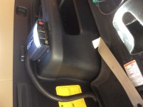
Not sure yet where it will go but maybe on top of wheel well near lift gate if that stays within the 10 ft wire length

Even thinking about replacing the current one, if that could be possible.
 
Last edited:
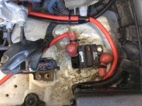
OK, here is what the inverter install looks like. Used a breaker rather than fuse, for easier “reset” over fuse.

At inverter mfg suggestion, used awg 2 wire to keep voltage drop well in spec for full use of 450W continuous 900W startup surge inverter AC output.

Since it is wired direct to battery, looking for a switch cover for inverter to keep from inadvertently turning it on. Alternative is just open the breaker when not in use.
 

Attachments

  • D9804D35-E8AC-44EC-B559-3184218AF7C5.jpg
    D9804D35-E8AC-44EC-B559-3184218AF7C5.jpg
    135.7 KB · Views: 460
  • 149DA533-65C6-429A-AF31-0178815022BD.jpg
    149DA533-65C6-429A-AF31-0178815022BD.jpg
    123.7 KB · Views: 455
OK, here is what the inverter install looks like. Used a breaker rather than fuse, for easier “reset” over fuse.

At inverter mfg suggestion, used awg 2 wire to keep voltage drop well in spec for full use of 450W continuous 900W startup surge inverter AC output.

Since it is wired direct to battery, looking for a switch cover for inverter to keep from inadvertently turning it on. Alternative is just open the breaker when not in use.

Looks good. One suggestion: those are pretty severe bends in the wires at the breaker. Over time, temperature cycling, and vibration they are likely to break or work loose. It would be better to rotate the breaker to have straighter wire lines. :thumb:
 
Looks good. One suggestion: those are pretty severe bends in the wires at the breaker. Over time, temperature cycling, and vibration they are likely to break or work loose. It would be better to rotate the breaker to have straighter wire lines. :thumb:

Yeah, thought about that so I am just keeping an eye on them
 

Members online

Forum statistics

Threads
278,310
Messages
3,554,080
Members
248,016
Latest member
Advally Service

Trending content

Back
Top