1000 watt inverter w/ a 2016... will the alternator keep up?

vjack

New member
I want to run a 1000 watt load off an inverter at a job site. I have one of those inverters that comes with jumper cables to run right off the battery but now I'm wondering if the alternator will be able to keep up. How much will the alternator put out at idle (or will the vehicle rev up if need be?) By my math a 1000 watt load is going to be ~80 amps.

I may be running it for a few hours so it would be a problem if I was slowly draining the 4Runner's battery.

Ideally I would have a small generator for this but it's not going to happen on short notice.
 
Register to hide this ad
I want to run a 1000 watt load off an inverter at a job site. I have one of those inverters that comes with jumper cables to run right off the battery but now I'm wondering if the alternator will be able to keep up. How much will the alternator put out at idle (or will the vehicle rev up if need be?) By my math a 1000 watt load is going to be ~80 amps.

I may be running it for a few hours so it would be a problem if I was slowly draining the 4Runner's battery.

Ideally I would have a small generator for this but it's not going to happen on short notice.

I doubt that you will be using all the 1000 watt constantly on a construction site, that is if you are using power tools (drills, saws, etc), they are used for a few minutes then the are off for a while. Thus, there will be no problem. Also, I doubt you will be using all the 1000 watts. Most power tools are far less than than that.

The car will not automatically rev up if the alternator cannot keep up with the load; you would have to do that manually which I doubt you want to do.

You might want to get a voltmeter and check the voltage from time to time. You can get some that plug into the cigarette lighter socket. If the voltage is constantly below 12 volts, the alternator is not keeping up.
 
I want to run a 1000 watt load off an inverter at a job site. I have one of those inverters that comes with jumper cables to run right off the battery but now I'm wondering if the alternator will be able to keep up. How much will the alternator put out at idle (or will the vehicle rev up if need be?) By my math a 1000 watt load is going to be ~80 amps.

I may be running it for a few hours so it would be a problem if I was slowly draining the 4Runner's battery.

Ideally I would have a small generator for this but it's not going to happen on short notice.

Following. I'm also interested in a good tire compressor if anyone wants to chime in.
 
I doubt that you will be using all the 1000 watt constantly on a construction site, that is if you are using power tools (drills, saws, etc), they are used for a few minutes then the are off for a while. Thus, there will be no problem. Also, I doubt you will be using all the 1000 watts. Most power tools are far less than than that.
[...]

I omitted the boring details but yes it is a 1000 watt load (8 amps @ 120v) and yes it will be running constantly. Not a power hand tool. So I do need to know at least the ballpark of what output I can expect from the 4Runner's alternator.

I do have a multimeter so that's a good idea of checking on it periodically so at least I don't end up with a dead battery.
 
I omitted the boring details but yes it is a 1000 watt load (8 amps @ 120v) and yes it will be running constantly. Not a power hand tool. So I do need to know at least the ballpark of what output I can expect from the 4Runner's alternator.

I do have a multimeter so that's a good idea of checking on it periodically so at least I don't end up with a dead battery.

Have you looked through this thread?: Getting more current from your stock alternator at idle
 

I did see that thread, but if you're going to go to al the trouble to get the accessory belt off and get a custom pulley for the alternator I would rather just get a HO alternate and not worry about running a stock one at 150% of its expected RPMs.

I'm really just asking what is the usable amps I can get from the stock alternator at idle, after the vehicle has taken what it needs to run the ECU etc.
 
Tagging along on an old thread.

I was inspired by Tinker's Adventures on utube and was working out the logistics of changing out the stock inverter (semi sine wave)in the rear of my rig. With a full sine wave inverter I could charge my sok batteries while moving locations to camp.

I would use the sok batteries to run cooking, lights etc at night.

So far I see the fuse in the engine bay is 80A for the stock inverter. Thus, the watts capacity is 80A x 12 v for 864 W (90% efficiency). I have not dug around back there to determine the wire size. ie did Toyota size the wires for 80A or for 400W.

If the wire is sized for 80A then I would go for a Renology 1000W as it is on sale (~$200)and has bluetooth reporting. If it is sized for 400W then I have not decided on a unit....

Any thoughts?
 
Last edited:
Tagging along on an old thread.

I was inspired by Tinker's Adventures on utube and was working out the logistics of changing out the stock inverter (semi sine wave)in the rear of my rig. With a full sine wave inverter I could charge my sok batteries while moving locations to camp.

I would use the sok batteries to run cooking, lights etc at night.

So far I see the fuse in the engine bay is 80A for the stock inverter. Thus, the watts capacity is 80A x 12 v for 864 W (90% efficiency). I have not dug around back there to determine the wire size. ie did Toyota size the wires for 80A or for 400W.

If the wire is sized for 80A then I would go for a Renology 1000W as it is on sale (~$200)and has bluetooth reporting. If it is sized for 400W then I have not decided on a unit....

Any thoughts?

Running an inverter to charge a 12v battery from 12v source is awfully wasteful.

In my experience the inverters in the rear of the 5th gens damage your starter battery over time. IE I had to replace my starter every 2 years while running my fridge / battery bank on the rear inverter during summer camping.

I recently picked up an Ecoflow River 2 Max. It charges at a much better rate off of only the 12v cig charger in the trunk. Something like 75w or more. The ecoflow I have does not like 120v though and will not charge at all in 100w or 400w modes, likely due to sine wave issues like you mentioned.

Last tidbit is you can couple the stock 12v and 120v at the same time to most battery banks through usb-C or multiple inputs, DYOR here but it will get you the fastest charge time without modifying the stock inverter.

If you really need 800+ watts then the stock setup will not do it for you. I would look at your power / camping needs before you go that far. The addition of a solar panel at camp is all I needed to be pretty off grid. Good Luck
 
In my experience the inverters in the rear of the 5th gens damage your starter battery over time. IE I had to replace my starter every 2 years while running my fridge / battery bank on the rear inverter during summer camping.
That's insanely unacceptable for a Toyota product. I should be able to use basic provided functionality without eating a $$ starter that often. Or one third that often.

Hopefully the new hybrid Tacoma/4Runner/Land Cruiser with the 2400W inverter doesn't eat through anything quickly. One day I'll just have an EV offroader directly pulling similar wattage off the big battery without any longevity concerns.
 
That's insanely unacceptable for a Toyota product. I should be able to use basic provided functionality without eating a $$ starter that often. Or one third that often.

Hopefully the new hybrid Tacoma/4Runner/Land Cruiser with the 2400W inverter doesn't eat through anything quickly. One day I'll just have an EV offroader directly pulling similar wattage off the big battery without any longevity concerns.

I completely agree. The saving grace is a decent battery warranty and dont buy the pro-rated toyota stealership ones either. Learned that the hard way too.

I think my issue is a combination of inverter age, inefficiency, and large battery temperature ranges throughout the year. my 2015 is pushing 10 years old but I have only ever pulled 120w max through the inverter and another 20-30w from 12v at once. Still on the original alternator which has never skipped a beat.

Worth the headache to have a fridge and battery bank in the trunk but like I recommended to OP inverters are an unnecessary step to add to what should be a 12v setup.
 

A stock Alternator is onlt 150 Watts . I watt is a Watt. It wont last long until the battery overheats and or the alternator pops..
 

A stock Alternator is onlt 150 Watts . I watt is a Watt. It wont last long until the battery overheats and or the alternator pops..
How does the rear outlet put out 400W if the alternator is 150W?

Can someone explain how the 400W 120V outlet works on the 5th gen, and if junk reliability using it is indeed a problem?
 
I think the 5th gen stock alternator is 130A.
If you have a SOK LiFePO4 battery in your vehicle that you want to use for cooking, lights, etc., the best way to charge it is a DC-DC charger, not an inverter. I have a RedArc BCDC1240D charger that pulls power off the stock alternator to charge my LiFePO4 auxiliary battery. That battery then powers a Giandel 1200W inverter in my cargo area, as well as a couple 12V fuse blocks. I use the inverter to power an induction cooktop that I only crank up to about 900W at most, since low to medium heat is all I need for the cooking I do. My LiFePO4 battery also powers a 12V fridge and some 12V fans and such. I have taken a few cross-country trips with this setup, and it works just fine, since bulk charging the LiFePO4 battery at 40A while driving replenishes the battery pretty quickly. No need for solar. I actually removed the OEM inverter on the rear passenger side wheel well while building out my rig, to make more room for other stuff.
 
I think the 5th gen stock alternator is 130A.
If you have a SOK LiFePO4 battery in your vehicle that you want to use for cooking, lights, etc., the best way to charge it is a DC-DC charger, not an inverter. I have a RedArc BCDC1240D charger that pulls power off the stock alternator to charge my LiFePO4 auxiliary battery. That battery then powers a Giandel 1200W inverter in my cargo area, as well as a couple 12V fuse blocks. I use the inverter to power an induction cooktop that I only crank up to about 900W at most, since low to medium heat is all I need for the cooking I do. My LiFePO4 battery also powers a 12V fridge and some 12V fans and such. I have taken a few cross-country trips with this setup, and it works just fine, since bulk charging the LiFePO4 battery at 40A while driving replenishes the battery pretty quickly. No need for solar. I actually removed the OEM inverter on the rear passenger side wheel well while building out my rig, to make more room for other stuff.

Did you use the stock wire or did you run new supply wires and if so what gauge?
 
Did you use the stock wire or did you run new supply wires and if so what gauge?

I ran new supply wires, 4 AWG.

I put a Blue Sea Systems 5191 Fuse Block Terminal on the starter battery positive terminal, and installed a 60A fuse in it (as recommended by RedArc for the BCDC1240D charger). Then a 4 AWG wire from that fuse block, to the rear of the engine bay, across the firewall, through a small hole on the passenger side of the firewall, into the passenger cabin area, to connect to the RedArc charger power input wire. This wire brings power from the alternator to the RedArc charger.

Now the wiring described above would provide power continuously to the RedArc charger, regardless of whether the vehicle is running or parked and turned off. I didn't want that, since that would drain the starter battery. So the wire that comes into the passenger cabin area from the firewall actually connects to a relay before it continues on to the RedArc charger. The other two terminals of the relay connect to a switch that I installed in the 4Runner dashboard, just in front of the center console. I push the switch to its On position to complete the connection in the relay so that power flows to the RedArc charger, and I push the switch to its Off position to break that connection inside the relay when I want to turn the RedArc charger off. The switch itself is powered by thin wires that go to an Add-a-Fuse in an ignition-switched socket in the OEM 12V fuse block under the steering wheel. This means that power will flow to the RedArc charger (which means the RedArc charger will be running and charging the LiFePO4 battery) only when two conditions hold: (1) the ignition is turned on, and (2) I have pushed the switch to the On position. The RedArc charger won't pull power from the starter battery (draining it) when the car is parked and turned off, and it won't charge the LiFePO4 battery unless I push the dashboard switch to On.

From the RedArc power output wire, a 4 AWG wire to another 60A fuse, on a Blue Sea Systems 2151 Dual MRBF Terminal Fuse Block installed on the positive terminal of the LiFePO4 battery. This wire carries the charging current from the RedArc to the LiFePO4 battery.

From the LiFePO4 battery negative terminal, a 4 AWG wire going back through the firewall on the driver's side, to the same ground point on the inner fender (near the starter battery) where the starter battery is grounded. So my LiFePO4 auxiliary battery system will have the same ground as the 4Runner starter battery.

The 2151 Dual fuse block on the LiFePO4 positive terminal has space for two fuses. The 2nd fuse is a 100A fuse. A 4 AWG wire from that 100A fuse brings 12V power to the 1200W inverter. 100A is a lot of current, so I installed my inverter fairly close to the LiFePO4 battery. If it were much further away, this wire would have to be 2 AWG or even thicker, and it's expensive and inconvenient to work with such thick wires.

This is a great wire gauge chart:
http://assets.bluesea.com/files/resources/newsletter/images/DC_wire_selection_chartlg.jpg
When determining the circuit length prior to consulting the chart, it's the entire round-trip circuit, from power source (such as the positive terminal of a battery), to the device being powered, and back again to the ground point. The length is not just the length of the wire from the power source to the device being powered.

 
A lot of good comments and expertise in this thread!

I've been watching the Bluetti Charger 1 for the past month since it came out. Very intriguing. Kinda expensive to add fast charging, but it does take a lot of the guess work out of it. Only big hassle is routing the wiring from the engine bay all the way back to the rear cargo area (or wherever) you plan on keeping your battery. One of the biggest complaint that I see is where they put the fuse-all the way back towards the end and not up close to the battery. I wouldn't want a live wire with the safety at the far end of things. But, I do believe it is fairly easy to re-wire.

I like that it is a smart charger (will detect when the car is on) and you have the ability to control it via the app.
 
Some tips on getting the 4 AWG wire through the firewall:

Ancor 4 AWG wire is 3/8" outer diameter. So a 9/16" diameter hole drilled through the sheet metal firewall would work well, if the insulation on the wire is protected by a high-temperature (silicone) grommet with 3/8" inner diameter. After drilling the 9/16" hole, I sanded the drilled edge and painted it with rustproofing paint.

A long, sharp awl can be used to poke a hole in the insulation mat behind the firewall. A bulkhead wire insertion tool like this, pushed through the 9/16" hole from the engine bay side of the firewall, might help to enlarge the hole in the insulation mat, making it easier to pull the thick wire through:
https://www.amazon.com/JEGS-Performance-Products-Insertion-Stainless/dp/B07952TMXL

Cut a coat hangar wire about 12" long and file/sand the ends smooth. Then duct tape one end of the coat hangar wire to the end of the 4 AWG wire. Tightly, but not using too many layers of duct tape, since the whole assembly needs to fit through the 3/8" grommet. It helps to lubricate the duct taped portion with spit before pushing it through the silicone grommet and the insulation mat. It also helps if a second person can grab the emerging end of the coat hangar wire from inside the front passenger footwell with a pliers and pull on it while you are pushing the 4 AWG wire through the firewall and holding onto the grommet to make sure it doesn't get pushed completely through the hole in the firewall. In case the grommet does get pushed into the space between the firewall and the insulation mat, it helps to have ordered a few of the silicone grommets. I found that pushing on the 4 AWG wire too hard or too fast would dislodge the grommet from the firewall, so take it slow.

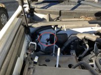
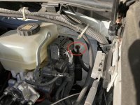
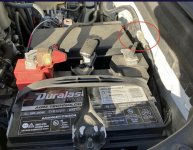
Below are pics of the 4 AWG positive wire passing through the firewall on the passenger side; the 4 AWG negative (ground) wire coming back through the firewall on the driver's side; and the ground point on the fender near the starter battery.
 

Attachments

  • 4 AWG wire on passenger side.jpg
    4 AWG wire on passenger side.jpg
    135.4 KB · Views: 193
  • 4 AWG ground wire in firewall.jpg
    4 AWG ground wire in firewall.jpg
    134.9 KB · Views: 207
  • 4 AWG ground point on fender.jpg
    4 AWG ground point on fender.jpg
    135.4 KB · Views: 204

Members online

No members online now.

Forum statistics

Threads
278,316
Messages
3,554,121
Members
248,016
Latest member
Advally Service

Trending content

Back
Top