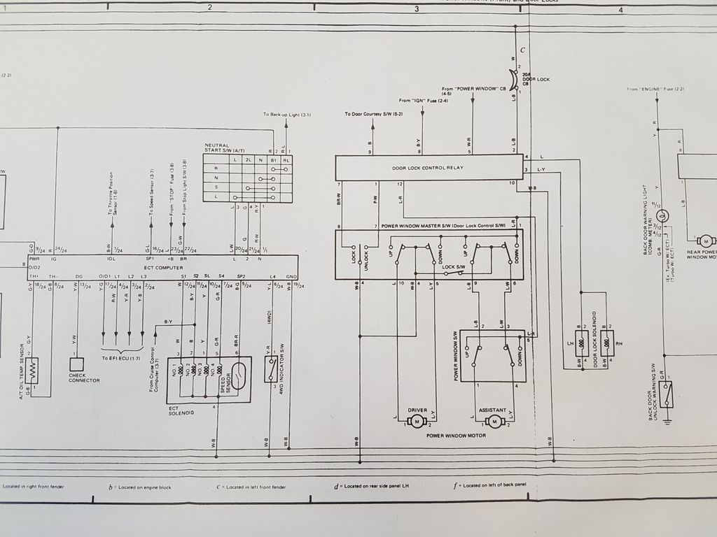
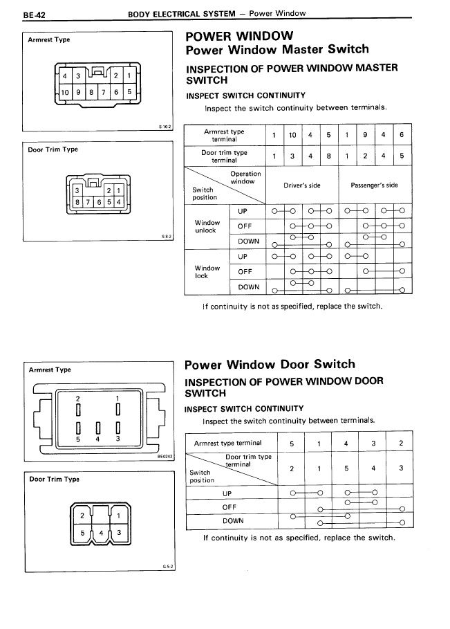
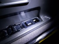
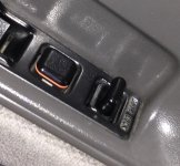
According to the wiring diagram the lock/unlock switch is just a SPDT center - off switch. You can get a rocker style switch like that at any automotive or marine store.
Those master panels are expensive to replace. Poke around eBay. Or just live with it til you can find one cheaper from a part out or junkyard. You can still lock the doors manually.
So that's a button which goes back to the middle possition, whenever I lock or unlock the doors. Is that correct?
Here's my pic from my 88


Need to start with the relay. Re-Wire it the way it should be wired:...
I'd like to install one (relay).
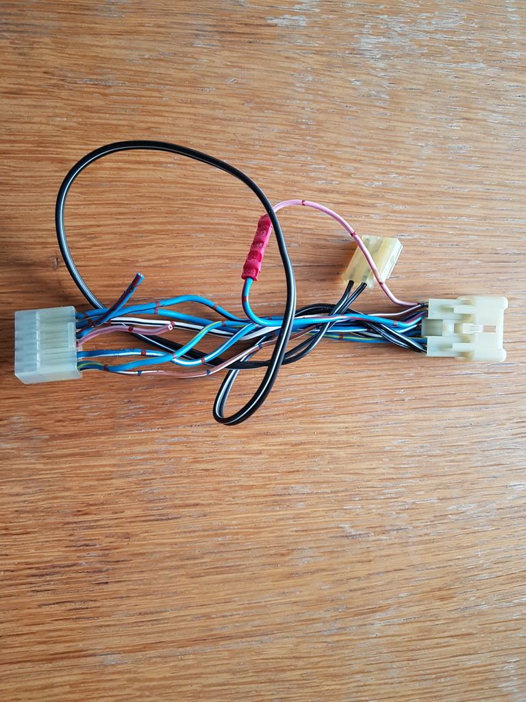
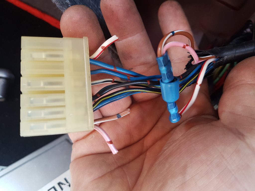
Yes, he modified it. You should not be able to operate doors or windows unless IGN is on. MOST LIKELY, he connected pin 12 directly to always on 12V.The PO did other changes, I can operate the driver, passenger and rear windows no key in the ignition switch. I think he did it to bypass the missing relay.
EXACTLY what results are you getting when you test pin 9 or pin 12?The pin 9 (black) and 12 (blue with red stripes) are the problem


Need to start with the relay. Re-Wire it the way it should be wired:
Pin 2 to Door Lock circuit breaker
Pin 5 to power window circuit breaker.
Pin 8 to IGN fuse.
Verify wiring to door solenoids.
Verify wiring of pin 9 to door courtesy switch.
Then we do functional test as I described above.
Yes, he modified it. You should not be able to operate doors or windows unless IGN is on. MOST LIKELY, he connected pin 12 directly to always on 12V.
EXACTLY what results are you getting when you test pin 9 or pin 12?
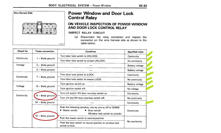
Correct, inspection procedure on the harness side of the relay connector.You are following inspection procedure ON THE HARNESS SIDE OF THE RELAY CONNECTOR with it disconnected from relay, correct?
Pin 12, I disconnected the window motors, the reading's as you say, no continuity to ground.Pin 9 should go to door courtesy switch. When doors are closed, there should be no continuity to ground. When any door or both doors are opened, there will be continuity to ground.
Inspection guide for Pin 12 is NOT accurate. Pin 12 gets 12V when certain conditions are satisfied. Continuity to ground will cause a short. The favorable result (when that procedure is followed - testing harness side) should say "READ RESISTANCE OF THE MOTOR". IF YOU DISCONNECT THE MOTOR THERE SHOULD BE NO CONTINUITY TO GROUND
![]()
Weird ones.
From the pin 9 I get these readings:
Driver door close - passenger door close : No continuity.
Driver door open - passenger door close : Continuity
Driver side open - passenger door open : Continuity
Driver side close - passenger door open : No continuity
I was expecting that, but I got No Continuity when I open the passenger door.Proper logic is:
If Driver side OR passenger open = continuity
If both are open = Continuity
I'm going to check the passenger courtesy switch.Yes, the courtesy switch on passenger side is either disconnected or broken or out of adjustment. Pretty simple to check. It's just a switch that closes when door is opened.
I'm looking at it right now, it's on the table, 30 years old Toyota door control module, part number 85980-89101.Will look into pin 12 later. BTW, do you already have the door lock relay?
...The PO changed the order of some pins from the master and passenger door switch small harnesses
Hi Someday,
Please restore above^^^ connection to stock based on schematic and we'll test that sub-assembly off the truck.
Reposting Schematic here for ease of reference:
Hi Someday,
Reposting Schematic here for ease of reference:
![]()
After checking the power window and door lock control relay connector (harness side) this is what I got:
D (Black) doesn't go low/zero when I open the passenger door, but it goes when I open the drivers door one.
And you got these readings at points A and B ON THE HARNESS?The power windows CB and door lock CB read 12V.
Now if you connect the window control relay to the harness, the harness should have power and "F" should now have 12V.F (Blue-red stripes) doesn't get 12V, the reading's zero.