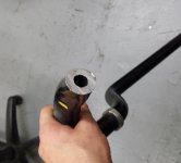
4th Gen Disconnecting Sway Bar Set-Up

BlackWorksInc

New member
So this has been something I have been planning for a long time now, those of you that wheeled with me before have heard me spout out some ideas for modifications and such and now I've decided to actually bring them to reality. I figured some of you would like to see the process of an idea turning into an real item so I'll be updating this with pictures and information as I go along.

So a little history on this idea; I drive my vehicles and by that I mean I drive them like I stole them. I have never understood why a person would spend obscene amounts money on a car to never drive it. So I really needed the use of my sway bar on my 4Runner, yet I wanted the benefits of a removed sway bar for off-roading. Unfortunately the design of our sway bars makes that very difficult, we can't just use disconnecting links like the majority of off-roaders. The limiting factor is that the sway bar hugs so tightly to the frame and suspension that removing the links presents the possibility that the swaybar can bind in the CV axle and/or spring in extreme cases.

There was a member on the FJ Cruiser forums who came up with a solution to this, and his idea is rather brilliant. Swaybar Disconnect, Check it out!!!! - Toyota FJ Cruiser Forum (I want to give credit to him, because it was his design that inspired me to create my own version.)

I felt that while his sway bar disconnect worked as intended, there were things that could be done to make the modification more functional and usable. I ended up with a design very similar in function to his, but with enhancements I felt made it more robust and easier to work with.

~

Now lets get to the technical stuff, If you look at the original sway bar from our friend on the FJ Cruiser forums you'll see that he decided to use two threaded bolts (I believe they are lug studs.) While this holds the sway bar parts together, I felt it was too cumbersome a design. I didn't want to have to dig out a ratchet and socket and then sit there and unbolt the damn thing, so I spent a lot of times trying to design a more efficient way to attach and detach the removable portion of the sway bar. Eventually I settled on using dual pins with holes for a modified lynch pin to slide in.

The next issue I felt needed to be addressed was that while the location of his disconnect was very accessible, it presented an issue for my rig in particular (and I assume a lot of others as well.) I run stock rims with 285/70R17's and they scrub at that exact spot on my sway bar on full turn. The bolts, nuts, and flanges would just tear up my tire if I did it that way. I spent weeks trying to design a functional, yet easy to remove shield to protect that portion and eventually just gave up, I found it much easier from a design standpoint to simply move the entire cut portion further in and avoid the scrub zone entirely. This still retained an easy to reach section where it could be disconnected from and would not affect turning radius of the wheel or damage the tires on my vehicle.

So with all these things in mind (I want to thank BLK4Runner for donating his sway bar for me to go over like a mad scientist!) I began with drawing up a 3D model of the design on SketchUp (one of Google's partners Free 3D design software) and after 3 or 4 iterations I came up with this:
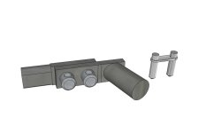
SBD-Bracket.jpg

I don't have access to the equipment I am going to need to produce this item at the moment so I have become a member of TechShop (TechShop is America's 1st Nationwide Open-Access Public Workshop -- What Do You Want To Make at TechShop?) and am taking their SBU (Safety & Basic Use) courses to use the required machining and fabrication equipment. This is going take most of the month, but I will try and update as I go along with the process!

I also have some machining tool bits, cutters, and other such things on order! (Techshop provides the equipment and training, but drillbits, toolbits, and ect are not provided. i.e. for the milling machine you supply your own endmills, ect.)

 

Attachments

  • SBD-Bracket.jpg
    SBD-Bracket.jpg
    47 KB · Views: 5,566
Register to hide this ad
Looking forward to this plan of yours. I to like the drive it like you stole it. I hated to have to remove the SB.

I have at times, look under there and possably there would be a way to modify the bends in the SB to make it functional. But, then with the lift and tires at full lock, not much room for bends, let alone the flexing. Good luck on this, will be on the look out for final completion.
 
Just curious, would there be any benefit to extended front links? I know several have switched to extended rears, thinking the same could be done for the front and be a compromise.
 
Subd! This is very exciting. After having an XJ on 35s my quick disconnect sways made a huge difference in articulation. But I ran into other issues with rubbing and had to modify my bump stops. Very curious to see how this is going to function with our rigs. Big ups to you blackworks!
 
Just curious, would there be any benefit to extended front links? I know several have switched to extended rears, thinking the same could be done for the front and be a compromise.

I have been debating about extended links (I have not yet decided what I am doing for the links.) most lift kits come with blocks to drop the sway bar down some to help prevent them from binding in the suspension and this does not seem to need longer links like the rear sway bar does. That is a very good question that I don't have an answer for.
 
So here's an update;

Finishing up the SBU's, got most of the tools in the mail, and am shopping around for material. Hopefully will start on the physical prototype next week sometime!

Here's what $700-ish worth of machining tools looks like, interwebz cookie for anyone that can answer what tools are pictured.

 
So here's an update;

Finishing up the SBU's, got most of the tools in the mail, and am shopping around for material. Hopefully will start on the physical prototype next week sometime!

Here's what $700-ish worth of machining tools looks like, interwebz cookie for anyone that can answer what tools are pictured.


Allen wrenches! I winzz!!
 
That's an interesting set-up, the issue is that you can't really use a set-up like that because of the clearance issues of the 120 Platform's Swaybar design. It works on Jeeps and such because they can run a straight rod from one end to the other easily, but with the 120 platform it needs to be offset bent in the center for clearance and curved at a couple sections to not contact the suspension components (this is also why a disconnecting link by itself will not be effective and could cause issues.)

To create something similar for the 4Runner/FJC/Tacoma you'd have to either create extended swaybar mounts (which would reduce clearance slightly and require a redesign of the skid plate to accommodate the taller mounts) or off-set bend the central portion like a stock sway bar; you'd then have to either machine or bend the side plates close to the original geometry of the sway bar to assure clearance in the entire suspension range of motion. Another issue is that you would not be able to effectively use that cam style selector where it is on the Jeep version because of the scrub angle. :(
 
Last edited:
Yeah... I wasn't assuming it would be a direct bolt-on application in any way. It would require some significant design work, but I like the concept of leaving everything in place and simply twisting to lock/unlock the sway bar... that's the part that would ideal!

I'm very much looking forward to your progress as I'd prefer to have the sway bar installed for street duty, but would like to experiment without it off-road.
 
Update-

I FINALLY found a supplier for 4140 bar & round stock, up until now I've almost been pulling my hair out. :mad: Have everything ready to go, but nothing to work with!
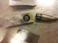
Anyways, as I said I have the material now so I'll start machining it tomorrow if I can reserve a Mill & Lathe. I bought some extra material to play around with welding on, since the 4140 has some pre and post heat needs.

Speaking of which, has anyone actually cut up one or broken one of their sway bars? It hit me after reading up on some sway bar materials that our bars might not be solid. I looked at the ends of the sway bar I have and it looks like it might be hollow; haven't gotten a chance to slice up the only sway bar I have as the welding jig to hold it in place is just a bunch of cardboard templates and I am still playing with the final design.

At least this is finally moving forward, should have some updates in the following week or so.
 
So ran into some issues with making the prototype, its just been a rough night.

Spent something like 5hrs tonight trying to at least get the brackets and holes cut... it didn't pan out the way I wanted it to...

Everything was going fairly good, I chipped the corners of my carbide endmill (not a big deal, still cuts great for what I need, just not gonna be able to do 90* plunge cuts) but managed to get two brackets to the size I needed them. Then came the annular cutter...

I have no experience with Annular Cutters and the information I found on multiple websites including manufacturer's stated to NOT peck the hole when drilling with an Annular Cutter; and tried to follow their instructions, feed, speed, ect. Started cutting fine until about 3/4 where the tool and workpiece soaked up too much heat, work hardened the 4140 and heated the annular cutter to the point the brazing failed. (That nib in the picture is one of the carbide bits that de-brazed)

So now I'm down a $70 Annular Cutter and almost back to square one.. (I think the smaller bracket is good still.) So I need to find out what I'm going to drill those 1" holes with... thinking to go with a HSS Annular Cutter and just flood it, but I'm not sure about tool longevity... then again at this point I'd like to actually MAKE A PART.

The result of 5hrs of work:
20130417_215609.jpg
 

Attachments

  • 20130417_215609.jpg
    20130417_215609.jpg
    61.1 KB · Views: 5,103
Hey, I got sidetracked into this thread and thought I would throw this your way:

A guy named Wes Beech runs a small outfit making custom Supra parts: http://www.beechperformance.com/html/toyota_products.html

He makes a set of adjustable length quick disconnects for drag racing. I had a set on my car... well, broke the quick disconnect at the track... but, the ball-socket assembly might be of use or interest to you. I'm certain that Wes would provide some advice.

Your double pin design, in my opinion, would be way, way way stronger... but most people aren't rolling these 4th gens over in the corners on big mud tires, haha!

Honestly, I've not been under my own truck to see the architecture of that assembly, but figured the info may be of use to you. Best of luck on this, I hope it works out!
 
So got a Hougen CopperHead to replace my old Jancy Slugger Annular Cutter and finished up the brackets. Was even able to salvage the one I partially cut before, the clearance is a little looser than I want (I think) but this is the prototype so I'll let it slide for now.

Going to reserve the lathe Wednesday and cut the pins down to length and chamfer the ends, hopefully drill the holes in them that night as well if a Mill is open. Haven't yet decided on the lynch pin design, but I'll deal with that when I get there. I still need to get some posterboard and finalize the stencils for the jig before I cut up the swaybar, but its moving along nicely.'

Here's a couple pictures to show what the connection looks like installed and uninstalled.

20130429_214039.jpg
20130429_214026.jpg
 

Attachments

  • 20130429_214039.jpg
    20130429_214039.jpg
    104.7 KB · Views: 1,571
  • 20130429_214026.jpg
    20130429_214026.jpg
    130.6 KB · Views: 1,531
Hey guys, been a little slow on the project; real life stuff, laziness, not feeling all that great, and crap.

Anyways, project isn't forgotten! I managed to get some material and weld up the jig for the sway bar and cut her up. I was just goofing off on the jig and ran out of gas somewhat so the welds are a little cruddy but it'll do what I need it to.

I also welded up a little of my extra 4140 without preheating and it seems to hold up pretty damn well, but I'm still going to preheat it to be on the safe side... once I figure out how I am going to do that.

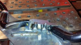
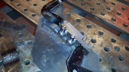
So here's a mock-up of what the completed disconnect portion should look like, I still need to grind the ends and strip the paint and weld it up, but this is about 85~90% finished I'd say.

Bar1.jpg
Bar2.jpg

Also, slight kink in my plans when I cut the sway bar in half. Turns out its not a solid bar like I had hoped. Shouldn't cause too much of an issue or affect the strength of the welds/joint in any significant way though.

20130521_210506.jpg
 

Attachments

  • 20130521_210506.jpg
    20130521_210506.jpg
    51.8 KB · Views: 2,736
  • Bar1.jpg
    Bar1.jpg
    60.9 KB · Views: 1,551
  • Bar2.jpg
    Bar2.jpg
    61.8 KB · Views: 1,528
This project has slowed down some, I apologize to those that are following it as I did say I should be done by now. :(

Its been a combination of real life issues, laziness, and some minor design issues.

Which brings me to my question/update. I'm hoping to finally weld up the sway bar and such sometime next week; the issue is with the physical sway bar link. I bought a pair of heim joints (expensive little buggers), unfortunately I don't think these particular joints will last long. They are stout enough for the application (their designed for industrial machinery, got them from a bearing supply company) but I think they joint itself will get contaminated/sticky after a while.

In any case, I am looking for a good set of aftermarket heim joint sway bar links for the 120 Platform, unfortunately the only ones I find are the AllPro Off-Road ones https://www.allprooffroad.com/034runnerfrontsuspension/268. There's a couple issues with them for what I need; the first being I only really need 1 sway bar link and they cost quite a bit. The second being that it looks like the misalignment spacers are part of the joint itself which makes my pin design unviable with these.

My question is, does anyone know a good supplier for the components? I need to find a metric heim joint with a 12mm ID, the majority of the Off-road websites sell "DIY" kits or parts for reasonable prices, but they are all standard for Jeeps or Domestics and I really need a Metric one. :mecry:

Any help would be greatly appreciated as I'm somewhat stalled at this point...
 
Update time!

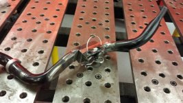
I'm 95-99% done! Its not the prettiest weld job, mostly operator error. I somehow mistook the MIG settings for 3/4" and forgot to turn the gas on so I had to grind out the first bead and reweld it. Then I forgot to account for the fact that I preheated the metal to 400+ degrees so the chart settings were actually too hot and made some of my welds a bit messy/runny/undercut; particularly on the round portion to the flat bar, so it looks a lot thicker than it probably should be... BUT! I am sure that while she ain't no looker, she's gonna take a beatin'!

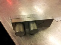
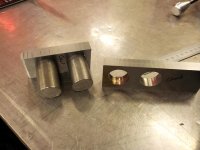
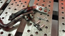
Anyways, So here's what the finished prototype joint looks like assembled and completely torn down. I am currently working on the quick release pin for the spindle side of the disconnecting portion, I might not finish it tonight; hopefully by the end of this week (I mean it this time, I swear! :ohwell: )

Assembled.jpg
Components.jpg

Anyways, after its all done I'll throw it on the 4Runner for a week or two and see how well it holds up.
 

Attachments

  • Assembled.jpg
    Assembled.jpg
    59.3 KB · Views: 1,611
  • Components.jpg
    Components.jpg
    60.8 KB · Views: 1,925
Eager to see this in action. I do prefer the feel of having the SB while on roading, but, know the advantage of having it removed for off roading.

They always say, the first one always cost you a fortune to make.
 

Members online

Forum statistics

Threads
278,315
Messages
3,554,104
Members
248,016
Latest member
Advally Service

Trending content

Back
Top