Another ARB Compressor Sanity Check

apc9199

Member
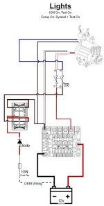
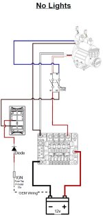
Trying to do a relatively simple ARB CKMA12 install under the hood and just want the switch located next to the compressor, not in the cab. I'm using a Blue Sea Systems SafetyHub 150 to allow for other future mods. I'm a little Type-A when it comes to this stuff and I'm not the greatest with electrical so I'm trying to make 100% sure I have everything right the first time. Can someone with experience doing this kind of stuff take a look and confirm/correct what I have so far?

Questions:
1. Since I have the SafetyHub 150, do I need the 40a fuse that comes as part of the ARB wiring harness? If so, should it go before or after the SafetyHub?
2. Should I include the diode after the fuse tap to prevent any weird feedback into the fuse/relay box? I figured I could just steal one from the ARB harness.
3. Hopefully I got my colors & pins correct. It is surprisingly hard to find complete info for this stuff online and I don't have the relay and harness in front of me right now. Let me know if any of the pins for the relay or switch don't look right.
4. Is it OK to tie the neutral for the compressor as well as the relay coil loop together to save a spot on the SafetyHub?

Thanks!

EDIT:

I updated the wiring diagrams after physically getting under the hood and learning a little more. I also added a second wiring diagram which allows for the use of the built-in lights in the ARB rocker switch. Once I understood how everything worked and could see it in action, adding the light wiring was trivial.

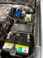
I also added a basic layout image of where the compressor and SafetyHub are in the engine bay. You can barely make out the relay mounted to the inner fender in the back. Directly in front of that is a cheap steel rocker switch mounting bracket I got on Amazon just to get the project done for now. You can also see the two red leads coming from the P-Outlet fuse under the dash. I confirmed there is no ignition-activated fuse under the hood so I used the under-dash one that others have recommended and ran the leads through the OEM grommet in the firewall.

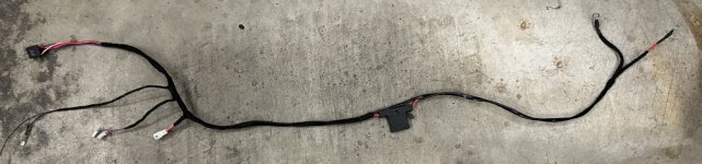
Finally, I added an image of my prototype wiring harness. Unfortunately I cut off the image of the two spade terminals that act as neutral for the switch lights. They are just two spade terminals wired in series as the diagram suggests. I currently have everything connecting straight to the battery because I don't have a 4awg Fuse adapter and I need the compressor for Memorial Day weekend. More info and better images to come once I have things a little more polished.

I think I'm going to downgrade to the BSS SafetyHub 100 due to size and the fact that I will never use the 10 circuits provided by the 150. That should give me just enough room to move the switch back to the Powertray and clean things up a bit. I may also move the quick-connect for the air line to the Powertray and use a remote-mount kit to feed it off the manifold. I don't like having the pressure switch and quick-connect mounted to the same port using a tee, it just looks amateur. When I have a little more time I'll get all of this done and do another update with better pics of everything along the way. Hopefully this will serve to help anyone in the future who is attempting this same thing and was frustrated trying to figure it out like I was.
 

Attachments
  • ARB CKMA12 Simple-NL.jpg
    ARB CKMA12 Simple-NL.jpg
    55.7 KB · Views: 58
  • ARB CKMA12 Simple-L.jpg
    ARB CKMA12 Simple-L.jpg
    60.6 KB · Views: 57
  • IMG_5928.jpg
    IMG_5928.jpg
    106.9 KB · Views: 59
  • IMG_5927.jpg
    IMG_5927.jpg
    92.9 KB · Views: 63
Last edited:
Register to hide this ad
OK, help me understand why using the safety hub with the arb wiring that includes the fuse? arb compressors draw lots of amps, I would wire right to battery to give the most reliable power delivery. if you don't like that arb in line fuse you can replace it with an inline circuit breaker.

you should use the diode, and just run the diode wires into the cab and use a fuse tap - there's a blank spot to do so. you can still have the switch under the hood. are you trying to remove the arb switch and use the arb switch harness? just trying to understand what parts of the harness/switch you are using
 
OK, help me understand why using the safety hub with the arb wiring that includes the fuse? arb compressors draw lots of amps, I would wire right to battery to give the most reliable power delivery. if you don't like that arb in line fuse you can replace it with an inline circuit breaker.

you should use the diode, and just run the diode wires into the cab and use a fuse tap - there's a blank spot to do so. you can still have the switch under the hood. are you trying to remove the arb switch and use the arb switch harness? just trying to understand what parts of the harness/switch you are using

The SafetyHub just allows things like lights and other accessories to be added in the future without continuously tapping the battery. It also allows for easy change over if I add a second battery someday, which I may do along with a solar charger. I don't have to rewire any of my accessories, I just run new wires from battery #2 to the SafetyHub and everything works again. In my diagram, you can essentially replace the SafetyHub with a battery and the rest is the same. I don't see a point in using the ARB fuse if the SafetyHub has its own built in fuse. That's why I was asking. I didn't want to eliminate it only to find out it should have been in there. ARB says to keep the fuse as close to the battery as possible, my SafetyHub will be no more than 2 feet away. Good enough, right?

The only parts of the ARB wiring I really plan on using are the relay and one of the diodes. I'll also use the ARB switch under the hood, mounted in a panel switch bracket. The rest will be custom built, soldered, shrink wrapped and loom taped to look like a factory loom. I haven't dug very deep to figure out the fuse tap situation. There has to be an ignition-switched fuse in the relay box under the hood, right? I plan on using a Bussmann Add-A-Circuit to tap into one there or, if need be, in the cab. This keeps the OEM wiring intact (no wire taps) and the same fuse on the original circuit.

TL_DR
Making my own custom wiring loom per the schematic above using the ARB relay, diode and switch. Trying to keep everything under the hood. Thoughts?
 
TL_DR
Making my own custom wiring loom per the schematic above using the ARB relay, diode and switch. Trying to keep everything under the hood. Thoughts?

OK. I understand a bit better now. IMO I would not use the safety hub. can it be used? sure, although with that amp draw I'd want to wire right to battery. just like a winch, those are best wired to a battery. with the arb wiring harness the fuse is just inches from the positive connection. you could of course use two fuses, the safety hub and arb fuse if you wanted to. are you planning on running multiple high amp accessories (compressor, winch, etc.)

In terms of the wiring/fuse tap. you can probably find one in the engine bay fuse box for IGN, but in the cab there is an empty spot with an IGN fuse (either 4 or 5 down on the right side looking up I believe). you don't even need to go through the firewall grommet, there is a smaller rubber grommet to the top left of it that you can drill out slightly and feed the wires through the rubber. it's 100% reversible in case you want to get rid of the compressor, just buy a new grommet. again engine bay works too I'm sure but then you're using a fuse tap on an existing fuse. personally I like to leave all the OEM as OEM as possible

I had an arb single with the switch wired up to my switch pros. I no longer have the compressor or switch pros but I still remember how I wired everything. I cut out the entire harness that had the lockers and switch wiring and just connected up on the main harness with the relay. I didn't use the diode but never had a problem
 
OK. I understand a bit better now. IMO I would not use the safety hub. can it be used? sure, although with that amp draw I'd want to wire right to battery. just like a winch, those are best wired to a battery. with the arb wiring harness the fuse is just inches from the positive connection. you could of course use two fuses, the safety hub and arb fuse if you wanted to. are you planning on running multiple high amp accessories (compressor, winch, etc.)

In terms of the wiring/fuse tap. you can probably find one in the engine bay fuse box for IGN, but in the cab there is an empty spot with an IGN fuse (either 4 or 5 down on the right side looking up I believe). you don't even need to go through the firewall grommet, there is a smaller rubber grommet to the top left of it that you can drill out slightly and feed the wires through the rubber. it's 100% reversible in case you want to get rid of the compressor, just buy a new grommet. again engine bay works too I'm sure but then you're using a fuse tap on an existing fuse. personally I like to leave all the OEM as OEM as possible

I had an arb single with the switch wired up to my switch pros. I no longer have the compressor or switch pros but I still remember how I wired everything. I cut out the entire harness that had the lockers and switch wiring and just connected up on the main harness with the relay. I didn't use the diode but never had a problem

The SafetyHub can handle 350 continuous amps with 4awg wire (which I'm using). If my compressor tries to pull more than that we have bigger problems. It also uses replaceable AMI fuses, so the compressor will be limited to 40 amps in the same fashion that the OEM harness would have provided, albeit slightly farther away from the battery. I don't have any plans for other high-amp accessories right now. Likely some combination of overhead lights, ditch lights and directional fogs. Possibly some rear-facing lights for camping as well. These will all be relatively low amperage. Even if I added a winch, my chances of airing up the tires while I simultaneously winch myself out of a crevasse are low! :heh:

I'll continue to research the fuse location. Still wondering if anyone see's any major flaws in my diagram also. I'd hate to wire this all up, flip the switch and watch the engine bay light up in flames!
 
Last edited:
I think the bssic safety concept for fuses is to prevent wiring overloads and electric fires. So fuse should be close to battery power source.
I am doing a similar Compressor hook up with a Smitty built compressor on a C4 fabrication bracket passenger side of engine room. I chose not to involve any factory 4runner circuitry. I'm coming off the battery with an in-line fuse about 1 foot from the battery. That 8 gauge wire goes to a Blue Sea 4 position power panel. It enters a high amp switch and then goes to the hot side of the BSpower panel. Then I go through its fuse to my compressor with 10 gauge. The BS panel ground goes to chassis ground.
So My plan is to open hood, turn on power to BS panel then use switch on compressor to activate it when wanting air.
Have 3extra positions- one for a GMRS radio and the other 2 for future lighting.
 
I think the bssic safety concept for fuses is to prevent wiring overloads and electric fires. So fuse should be close to battery power source.
I am doing a similar Compressor hook up with a Smitty built compressor on a C4 fabrication bracket passenger side of engine room. I chose not to involve any factory 4runner circuitry. I'm coming off the battery with an in-line fuse about 1 foot from the battery. That 8 gauge wire goes to a Blue Sea 4 position power panel. It enters a high amp switch and then goes to the hot side of the BSpower panel. Then I go through its fuse to my compressor with 10 gauge. The BS panel ground goes to chassis ground.
So My plan is to open hood, turn on power to BS panel then use switch on compressor to activate it when wanting air.
Have 3extra positions- one for a GMRS radio and the other 2 for future lighting.

GMRS radio tip. if you have interference wiring to the breaker, wire the radio positive/negative right to battery. vehicles are very noisy when it comes to radio and it doesn't take much to create noise. I had my ham wired to battery and it worked quite well with hardly any interference from the vehicle on VHF/UHF. the issue was all the other line of sight blockers...
 
I think the bssic safety concept for fuses is to prevent wiring overloads and electric fires. So fuse should be close to battery power source.
I am doing a similar Compressor hook up with a Smitty built compressor on a C4 fabrication bracket passenger side of engine room. I chose not to involve any factory 4runner circuitry. I'm coming off the battery with an in-line fuse about 1 foot from the battery. That 8 gauge wire goes to a Blue Sea 4 position power panel. It enters a high amp switch and then goes to the hot side of the BSpower panel. Then I go through its fuse to my compressor with 10 gauge. The BS panel ground goes to chassis ground.
So My plan is to open hood, turn on power to BS panel then use switch on compressor to activate it when wanting air.
Have 3extra positions- one for a GMRS radio and the other 2 for future lighting.

Yes, fuses need to be as close to the battery as possible. The longer the length of wire between the battery and a fuse, the more risk there is of massive trouble if that wire gets compromised and shorts to ground. Any of the wire between the battery and fuse is unprotected.

For the worst case, think of a car accident that pinches an unfused wire somewhere and causes a fire where the car would otherwise have been completely repairable but now is a smoldering hunk of trash.
 

Members online

Forum statistics

Threads
278,309
Messages
3,554,071
Members
248,016
Latest member
Advally Service

Trending content

Back
Top