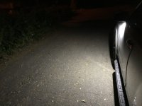
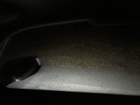
Anytime Control of Mirror Puddle Lights: Use as Ditch Lights

ElectroBoy

Banned
When I installed the MESO Puddle Pod lights upgrade in the external mirrors of my 5th Gen 2018 ORP last year, I was impressed with how bright they were and the throw of the LED beams to the sides. Instead of just the automatic illumination when the doors were unlocked with the remote, I wanted the ability to control them anytime to use as ditch lights.

4 Runner Puddle pods
– MESO CUSTOMS LLC


Last summer MESO hinted in an email that there was an upcoming switch/harness product for the 4Runner to do just that. It is still not here, but there *is* a MESO product for the 3rd Gen Tacoma: Tacoma Puddle Switch Kit.

Tacoma Puddle Switch Kit
– MESO CUSTOMS LLC


I was having trouble finding the proper switch, so on the recommendation of [MENTION=150567]Old Red[/MENTION] I ordered the MESO product, primarily for the custom On-Off-On switch and its interface connector, to be used for the functions of Anytime On, Off, or Automatic (like OEM). Old Red provided the technical advice for how to implement this and it worked out well. Here is how I did it.
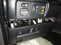
(Photo from MESO website)
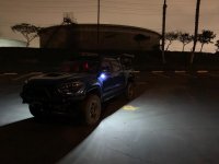
 

Attachments

  • BAD000AB-0ABD-4346-A89F-4BE237E7C70C.jpeg
    BAD000AB-0ABD-4346-A89F-4BE237E7C70C.jpeg
    35 KB · Views: 4,321
Register to hide this ad
Usually the most daunting task for me is figuring out how to access the wiring. This first section is about how to do that.

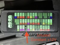
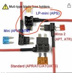
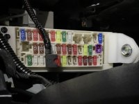
1. You will need a fused source of constant +12V. If you do not have this readily available from a previous mod, use a voltmeter to find an unused location on the fuse block. Install a Low Profile (LP) Mini fuse add-a-circuit tap, with a 10 A fuse in the top location, and verify that the +12V is available at the tap’s crimp output wire. This will be used in a later step. (I also use the MESO Extended Fuse Box Cover).
2. Remove the power, disconnect the battery GND terminal.
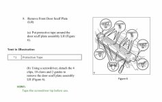
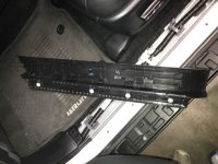
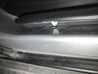
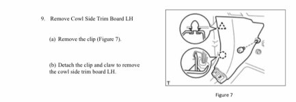
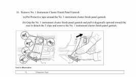
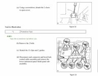
3. Remove the plastic driver side door scuff (sill) plate. Note where the white tabs are underneath. Here’s some photos and the Toyota instructions.
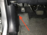
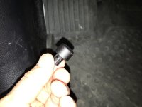
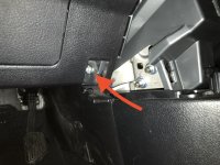
4. Remove driver cowl side trim (kick) board. First remove the round plastic cover down by the dead pedal. Use a small blade screwdriver in one of the holes to spin the whole thing counter clockwise and off. Pull the panel toward you to release tab at the top. Look behind the panel and see the clip toward the floor. I used as long shafted screwdriver to release the cover from it.
5. Remove the left hand garnish piece under the Fan control knob.
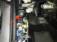
6. Remove the lower instrument panel. There are two bolts and 13 clips. Carefully pull the panel forward from the top to release the individual clips as you work around the edges of the panel. You can remove the ebrake cable if you like, I left it attached and just layed the panel on a towel
 

Attachments

  • 1DB03E16-8EEE-4AD2-B25E-F2B98673BA17.jpeg
    1DB03E16-8EEE-4AD2-B25E-F2B98673BA17.jpeg
    105 KB · Views: 3,943
  • F00990BC-56A3-48F4-BACF-3D4AC36495EC.jpeg
    F00990BC-56A3-48F4-BACF-3D4AC36495EC.jpeg
    107.7 KB · Views: 3,769
  • B45940B5-A031-43D1-9AA1-3527E15895F5.jpeg
    B45940B5-A031-43D1-9AA1-3527E15895F5.jpeg
    76.2 KB · Views: 3,784
  • 04A4313C-426D-4D2C-A3B3-AF7B8E12810A.jpeg
    04A4313C-426D-4D2C-A3B3-AF7B8E12810A.jpeg
    68.1 KB · Views: 3,749
  • 44BB7165-14EB-4A70-B5E1-2EF3D7A7D132.jpeg
    44BB7165-14EB-4A70-B5E1-2EF3D7A7D132.jpeg
    97.7 KB · Views: 3,692
  • 57DC6523-9AC8-4661-BCF3-46F1889BC5CA.jpeg
    57DC6523-9AC8-4661-BCF3-46F1889BC5CA.jpeg
    88.3 KB · Views: 3,754
  • 514F0A6E-8601-4288-BA2C-3EA9611DB27F.jpeg
    514F0A6E-8601-4288-BA2C-3EA9611DB27F.jpeg
    33.1 KB · Views: 3,633
  • 31584AEA-CADC-4A50-A942-4F017EE8BC59.jpeg
    31584AEA-CADC-4A50-A942-4F017EE8BC59.jpeg
    90.1 KB · Views: 3,640
Last edited:
More photos.
 

Attachments

  • C6308F87-26E8-48D8-ACDF-5D74EE0AD30B.jpeg
    C6308F87-26E8-48D8-ACDF-5D74EE0AD30B.jpeg
    66 KB · Views: 3,676
  • 44AED5EF-71F9-4999-948C-3F75085566BA.jpeg
    44AED5EF-71F9-4999-948C-3F75085566BA.jpeg
    101.7 KB · Views: 3,691
  • 7119CB51-263C-46AE-A0A0-EC25A37B60A3.jpeg
    7119CB51-263C-46AE-A0A0-EC25A37B60A3.jpeg
    98.5 KB · Views: 3,719
  • 99C2C5BC-4E0E-45E4-A29D-A5C49829CDE7.jpeg
    99C2C5BC-4E0E-45E4-A29D-A5C49829CDE7.jpeg
    69.1 KB · Views: 3,843
  • C0AA38D7-63AF-4949-8DBE-44CEC47041D5.jpeg
    C0AA38D7-63AF-4949-8DBE-44CEC47041D5.jpeg
    89.6 KB · Views: 3,640
  • C6F71579-08B2-442D-BFAE-103EA535EA26.jpeg
    C6F71579-08B2-442D-BFAE-103EA535EA26.jpeg
    102.7 KB · Views: 3,710
  • 1B93DAEF-62C4-4824-8112-118379F92834.jpeg
    1B93DAEF-62C4-4824-8112-118379F92834.jpeg
    112.4 KB · Views: 3,678
  • 30BD1C47-BBDD-4FEF-8957-7A3FD7D4D4A7.jpeg
    30BD1C47-BBDD-4FEF-8957-7A3FD7D4D4A7.jpeg
    104.5 KB · Views: 3,631
Last edited:
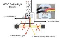
(The Wiring Diagram is attached below.)

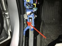
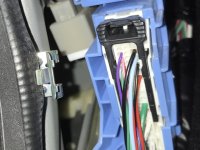
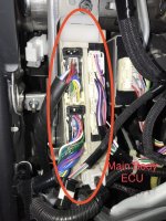
7. Now you have access to the Main Body ECU which outputs the Mirror Illumination line (MILE).
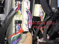
8. The MILE line is on connector F10 pin 4. It’s a larger diameter wire (14AWG) than the others in that connector. Color is White.
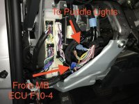
9. Cut this wire in a convenient location where you can work on it. You can peel back some of the tape and wire loom as needed. I stripped the insulation and crimped spade lugs on each cut end, one female and one male in case I ever want to reverse this mod.
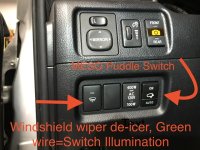
10. Install the On-Off-On switch in a blank spot in the panel.
11. Refer to the marked-up switch diagram and the Toyota wiring diagram. Familiarize yourself with the connector that plugs into the back of the switch. The following description references this particular MESO switch. Note that there are 3 Black wires. The two on the top row are for switch backlight illumination. The other one on the bottom row is the output of the “On” contact. Refer to the Meso switch diagram to get the orientation.
12. You need to cut apart the two Black wires that are crimped together (one from top row, one from bottom row). Connect the top row Black wire to a chassis GND bolt for switch illumination return. Leave the circular lug on this wire if you wish. You may have to extend this wire for extra length.
13. The other Black wire (on bottom row) you cut away will be used to supply the constant +12V to the switch, when it’s active in the “On” position. Solder or crimp a longer length of wire to this and connect it to the fuse box fuse tap output wire you installed in step 1.
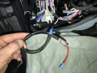
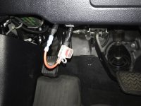
14. Connect the Yellow wire to one side of an in-line 10A fuse holder, solder or crimp. Connect the other side of the fuse holder to a spade lug of the correct type and mate it with the MILE output wire from the Main Body ECU, F10-4. This supplies the Automatic +12V to the switch. Extend the wires as needed so you can pull down and access the fuse easily for replacement. (See #5 in the Notes section below).
15. Connect the RED wire (the Common pin of the switch) to a spade lug of the correct type and mate it to the other end of the cut MILE line, which supplies the power to the external mirror puddle lights.
16. The Black wire in the center of the top row is the Illumination+12V input to the switch. Connect it to the illumination+12V wire of another switch. I connected it to the Green wire of the windshield wiper heater switch.
17. Check all your connections, connect the battery, and test out the switch. First in “On” mode. Then in “Automatic” mode with the remote (or push in the door button).
18. If everything works, secure your wiring with zip ties or tape, put all the panels back together, and enjoy your new ditch lights!
 

Attachments

  • 27889D8B-790B-41B8-B991-D409E6572FAE.jpeg
    27889D8B-790B-41B8-B991-D409E6572FAE.jpeg
    132.3 KB · Views: 3,902
  • CC985A7D-E638-4883-8233-DEBE24F9180C.jpeg
    CC985A7D-E638-4883-8233-DEBE24F9180C.jpeg
    130.4 KB · Views: 3,673
  • 00288FD7-2C48-4CA5-BE67-CEF7F8E84E0D.jpeg
    00288FD7-2C48-4CA5-BE67-CEF7F8E84E0D.jpeg
    112.2 KB · Views: 5,359
  • 0E67FC2D-D5BE-4977-B91E-7BD54F338A84.jpeg
    0E67FC2D-D5BE-4977-B91E-7BD54F338A84.jpeg
    129.4 KB · Views: 4,502
  • 1168BB4D-662D-42B6-BF38-620AEFD55A89.jpeg
    1168BB4D-662D-42B6-BF38-620AEFD55A89.jpeg
    76.6 KB · Views: 4,650
  • 73DDB462-A975-4279-9A80-263FA9DE3391.jpeg
    73DDB462-A975-4279-9A80-263FA9DE3391.jpeg
    116.2 KB · Views: 3,592
  • AnytimePuddleLights150.PDF.pdf
    AnytimePuddleLights150.PDF.pdf
    704.4 KB · Views: 687
  • 5EEF8F5C-AACD-4C86-A53B-3E75AA6C28EB.jpeg
    5EEF8F5C-AACD-4C86-A53B-3E75AA6C28EB.jpeg
    94.4 KB · Views: 3,617
Last edited:
Notes:

1. If you crimp, make sure the connections are secure. I prefer to solder.

2. I like to use wire loom sleeving to protect my added wires from abrasion.

3. For long wire lengths secure them with tape or zip ties to keep them in place.

4.The thin 22 AWG wire on the switch connector, and the illumination wire, are hard to crimp to or wire tap. For an in-line connection on these wires I prefer to shave a small section of insulation off with an Xacto blade and solder a wire for a more reliable connection. Insulate with tape or heat shrink tubing.

5. The Toyota wiring diagram has a note (*17) that the 10A "Mirror" fuse circuit was included from August 2018 production forward. This would be to protect the Main Body ECU if a puddle light was shorted to GND. So your 4Runner may already have this "Mirror" fuse included. I'm not sure where this fuse would be located.

6. MESO's gear sells out quickly. Other vendor's switch pinouts and wire colors will be different.
 
Last edited:
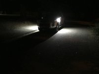
Night shots.
Puddles only.
Driver’s side.
Looking out passenger side window.
 

Attachments

  • 347552C7-0FF3-4401-AC39-248B7723EBC6.jpg
    347552C7-0FF3-4401-AC39-248B7723EBC6.jpg
    73.5 KB · Views: 3,646
  • 101E8E86-2561-403E-9DDA-8248AC68BDB6.jpeg
    101E8E86-2561-403E-9DDA-8248AC68BDB6.jpeg
    87.9 KB · Views: 3,365
  • 1F340227-6697-4DC9-9ABB-E5423125F53B.jpeg
    1F340227-6697-4DC9-9ABB-E5423125F53B.jpeg
    60.4 KB · Views: 3,374
Last edited:
I saw that meso is creating a version for the 4runner currently. not sure when it will be released though

That’s what I was waiting for, a solution that MESO figured out. The puddle control switch and harness for the Tacoma was announced last August 2019 and it’s available now. I contacted Meso in March 2020 asking about the 4Runner product. The response was “We don't have a control switch for the 4Runner puddles at this time.” I think Meso’s products are great. But most of them are “coming soon”. So if you can find an On-Off-On switch that fits, here’s how to do it.
 
After an unsuccessful first install meso provided a second harness and it turned out the first one was defective, been looking forward to this since picking up the meso puddle lights last year, also went ahead and rearranged the switches from factory. Looking forward to the map lights to match the dome light.

TlsmJz7.jpg

UHOEIWG.jpg

ehXNB8o.jpg

UBUXJC7.jpg
 
After an unsuccessful first install meso provided a second harness and it turned out the first one was defective, been looking forward to this since picking up the meso puddle lights last year, also went ahead and rearranged the switches from factory. Looking forward to the map lights to match the dome light.

Where did you tap into the 12v illumination for the switch?
 
After an unsuccessful first install meso provided a second harness and it turned out the first one was defective, been looking forward to this since picking up the meso puddle lights last year, also went ahead and rearranged the switches from factory. Looking forward to the map lights to match the dome light.

TlsmJz7.jpg

UHOEIWG.jpg

ehXNB8o.jpg

UBUXJC7.jpg

Do you have any details on the install instructions? I can’t find them anywhere and I just picked this kit up.
 
Where did you tap into the 12v illumination for the switch?

See the enclosed wiring diagram above.

Connect wires to the Wiper warmer switch:
Gray - dimming ground
Green - 12V illum power

I just used a regular chassis ground, so my switch backlight does not dim.
Note that these wires are very small gauge. I used an exacto razor blade knife to carefully slice off some insulation to expose the wire and soldered to it. Be sure to insulated and strain relieve with tape or cable ties so you don’t tug on them too much after installation.
 
After an unsuccessful first install meso provided a second harness and it turned out the first one was defective, been looking forward to this since picking up the meso puddle lights last year, also went ahead and rearranged the switches from factory. Looking forward to the map lights to match the dome light.

TlsmJz7.jpg

UHOEIWG.jpg

ehXNB8o.jpg

UBUXJC7.jpg

I finally got around to installing mine, what was defective about yours? Mine don’t seem to turn off if I leave it in auto mode even with the truck started.
 

Members online

Forum statistics

Threads
278,316
Messages
3,554,120
Members
248,016
Latest member
Advally Service

Trending content

Back
Top