
Battery/Alternator issue. Voltage is OK

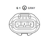
That is looking at the face of the plug. The wires leave out the back. The lock is on the top which is kind of obvious. The numbers correspond to the numbers on the wire diagram which also shows the colors. I could write them down for you, but all the info is there and it is better to learn how to do it that be told the answers.


Please do not think I am lazy and would rather listen to answers rather than look up answers. Saying those numbers are the same the drawing numbers is what I was wanting to clarify. You could have easily done that rather than assume I'm lazy. Look at my job description. This stuff is not even close to my first rodeo. Just because you don't see me respond much to gauge if you consider what I post worthy of reading doesn't mean a lazy idiot.

I worked with a guy that looked at things differently than me at work and until I figured out his perspective it was not fun.


Sent from my iPhone using Tapatalk
 
Please do not think I am lazy and would rather listen to answers rather than look up answers. Saying those numbers are the same the drawing numbers is what I was wanting to clarify. You could have easily done that rather than assume I'm lazy. Look at my job description. This stuff is not even close to my first rodeo. Just because you don't see me respond much to gauge if you consider what I post worthy of reading doesn't mean a lazy idiot.

I worked with a guy that looked at things differently than me at work and until I figured out his perspective it was not fun.


Sent from my iPhone using Tapatalk
Hey. Cool your jets. I was just explaining why I didn't write them down. I didn't say you were lazy, I just said it was better to learn how to do it than be told the answer. But if you don't like my help I'll take it elsewhere.

What job description?
 
Last edited:
Reading the schematic

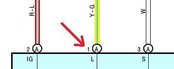
[MENTION=10169]TheDurk[/MENTION], am I reading the schematic correctly? Don't these small numbers at the regulator correspond to the plug numbers?
 

Attachments

  • alt numbers.jpg
    alt numbers.jpg
    9.8 KB · Views: 345
  • alt plug.jpg
    alt plug.jpg
    12.8 KB · Views: 372
[MENTION=10169]TheDurk[/MENTION], am I reading the schematic correctly? Don't these small numbers at the regulator correspond to the plug numbers?

absolutely--well to be picky, to the terminal or pin numbers shown on the plug drawing. The plug number is G1. And the A on the wire matches the A on the plug for when you have devices with more than one plug.
 
Last edited:
Hey. Cool your jets. I was just explaining why I didn't write them down. I didn't say you were lazy, I just said it was better to learn how to do it than be told the answer. But if you don't like my help I'll take it elsewhere.

What job description?


That's ok, jets cooled. I was just wanting to clarify the wiring to look at my drawings to help explain what is going on. Most 1 wire Alts are the same and the wire with the highest voltage is only 12.25v. I think that wire is the sense wire and should be system voltage. But wanted to be sure of the "pin out"

That bulb has a very specific job. The fact that it's glowing and system voltage is above 15v and the highest voltage on that plug is only 12.25v means something.

On the CJ7 one of those wires is gaged to the alt output. And the option is to run that wire to the battery. But factory is jumped over to the alt output.


Sent from my iPhone using Tapatalk
 
That's ok, jets cooled. I was just wanting to clarify the wiring to look at my drawings to help explain what is going on. Most 1 wire Alts are the same and the wire with the highest voltage is only 12.25v. I think that wire is the sense wire and should be system voltage. But wanted to be sure of the "pin out"

That bulb has a very specific job. The fact that it's glowing and system voltage is above 15v and the highest voltage on that plug is only 12.25v means something.

On the CJ7 one of those wires is gaged to the alt output. And the option is to run that wire to the battery. But factory is jumped over to the alt output.


Sent from my iPhone using Tapatalk

System voltage is only 15V with the engine running. The 12v readings are with the engine off.

What I can see is that the Sense or #3 wire (see the S?) is reading 0V so it is not connected to the battery as it should be, so it is not sensing what it is supposed to sense. So the alt ramps up to its max which is not good for the system. Need to fix that before he worries any more about the light, but I suspect if he fixes that he'll fix the light, too.
 
Last edited:
System voltage is only 15V with the engine running. The 12v readings are with the engine off.

What I can see is the that the Sense or #3 wire (see the S?) is reading 0V so it is not connected to the battery as it should be, so it is not sensing what it is supposed to sense. So the alt ramps up to its max which is not good for the system. Need to fix that before he worries any more about the light, but I suspect if he fixes that he'll fix the light, too.

:cheer2:

OK I got this, I speak El Durko!

Alt-S is the stator or sensing circuit if you go back to external mechanical regulators. On a typical GM style alternator with a TWO wire plug, you have F(field) which is the light circuit/excitation circuit, and the S which was typically a simply jumper to the BAT post on the alternator.

So wire # 3 MUST SEE BATTERY VOLTAGE!
:whistle:
 
That makes sense. but wanted to see pinout to see what each wire does. The Si alt upgrade from GM is basically the same thing and wanted to see the wire designation. The adapter you buy for the GM to Toyota lines the wires up to their correct pin.

Some Alts full fielded push 18v (my grand Cherokee comes to mind) the Denso only full fielding at 15v must be their design.


Sent from my iPhone using Tapatalk
 
Last edited:
absolutely--well to be picky, to the terminal or pin numbers shown on the plug drawing. The plug number is G1. And the A on the wire matches the A on the plug for when you have devices with more than one plug.

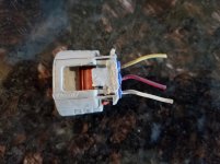
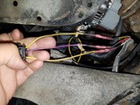
Ok, before shorten my harness to swap some wires around, here is what I have.

First picture is the original plug (which you see is extremely haggered). Top down is Yellow, Red, White. This correlates with the schematic and plug terminals noting Wire #1 = Yellow, Wire #2 = Red, and Wire #3 = White.

The second picture is what I spliced in place of the old. All I did was match to position of the previous wires.

Still think I wired it incorrectly? I'm all ears...
 

Attachments

  • 20170120_164256.jpg
    20170120_164256.jpg
    130.2 KB · Views: 487
  • 20170120_164625.jpg
    20170120_164625.jpg
    136.6 KB · Views: 394
It looks like a fuse feeds that "Sense wire".


Sent from my iPhone using Tapatalk

Replaced and tested with 3 known good fuses... I have continuity from battery to fuse, beyond that I have zero continuity to all 3 of the plug terminals. Maybe I have a break somewhere after the fuse since I don't have power?
 
Replaced and tested with 3 known good fuses... I have continuity from battery to fuse, beyond that I have zero continuity to all 3 of the plug terminals. Maybe I have a break somewhere after the fuse since I don't have power?


That is where you need to start. I'll try and post a drawing. I'm not at garage to use my wiring drawings. But Internet and google images works in a pinch.


Sent from my iPhone using Tapatalk
 
That is where you need to start. I'll try and post a drawing. I'm not at garage to use my wiring drawings. But Internet and google images works in a pinch.


Sent from my iPhone using Tapatalk


It looks like the EA1 box may be a connector
0e5a7938da7418b60b1788cb6865d4e4.png


Sent from my iPhone using Tapatalk
 
It looks like the EA1 box may be a connector


Sent from my iPhone using Tapatalk

Why would you use a clip of the overall wiring diagram from the WRONG year when I posted the SPECIFIC and CORRECT YEAR diagram upthread? You are just injecting confusion.

That said, your conceptual approach is correct.

The detailed diagram I posted explains that the EA1 connector is the junction between the Engine No. 2 Wire and the Engine Room Wire (near the Engine Room R/B) aka the main fuse box. The location and pin-out of Connector EA1 are shown below on pages 36 & 37 respectively. Need to split that connector and see if you are getting power from the upstream side and if you have continuity to Pin #3 on the alt plug going downstream. The white wire from Pin #3 on the alt to the ALT-S fuse in the main box lands at Pin #4 of the EA1 connector.

Presumably one of those cases I described above will indicate a fail, and we go from there.
 

Attachments

Last edited:
:cheer2:

OK I got this, I speak El Durko!

Alt-S is the stator or sensing circuit if you go back to external mechanical regulators. On a typical GM style alternator with a TWO wire plug, you have F(field) which is the light circuit/excitation circuit, and the S which was typically a simply jumper to the BAT post on the alternator.

So wire # 3 MUST SEE BATTERY VOLTAGE!
:whistle:

I hear what your saying. I'm trying to process several opinions and suggestions right now. Looking at my photos, can you or do you agree that I wired it correctly? And do you know where the EA1 (4-wire) plug/connector is? I am in and out of my house trying to figure this thing out because I don't have a garage and its already 20F out there.
 
Ok, before shorten my harness to swap some wires around, here is what I have.

First picture is the original plug (which you see is extremely haggered). Top down is Yellow, Red, White. This correlates with the schematic and plug terminals noting Wire #1 = Yellow, Wire #2 = Red, and Wire #3 = White.

The second picture is what I spliced in place of the old. All I did was match to position of the previous wires.

Still think I wired it incorrectly? I'm all ears...

No, I see now you did it right, but we need battery power from the Alt-S fuse to the white wire on Pin #3 at the alt to fix this. Sorry, I misinterpreted your results first time around. So do the test I describe in the post above, and if the fail is downstream, then I suggest you remake that butt splice on the white wire and retest. It looks good, but there has to be a break somewhere. If the fail is upstream, we need to look inside the fusebox.

Also, it won't hurt to carefully do a visual check of that harness all the way from the fuse box to the alt for any sign of physical damage.

Good news is we can always just run a whole new wire from fuse box to alt if we can't find the break. But I'd prefer to fix it.

You're from MT--do you by any chance have a Canuck rig with DRLs? I was assuming no DRLs on a '97.
 
Last edited:
I hear what your saying. I'm trying to process several opinions and suggestions right now. Looking at my photos, can you or do you agree that I wired it correctly? And do you know where the EA1 (4-wire) plug/connector is? I am in and out of my house trying to figure this thing out because I don't have a garage and its already 20F out there.

You posted this while I was typing my answer to your previous post. Hopefully I had already covered your other questions in post #76. For the record, the good Dr. IBall and I are on the same page, as usual.
 
Last edited:
First off, let me say thank you to everyone assisting with this. I understand the concepts of electrical, just not too good at troubleshooting.

[MENTION=10169]TheDurk[/MENTION]: no Canuck model, no daytimes.

I found the EA1 plug.
I have continuity from EA1, terminal #1 to wire #2 @ the alternator.
I have continuity from EA1, terminal #2 to wire #1 @ the alternator.
I have continuity upstream from EA1, terminal #4 to the fuse.

I DO NOT have continuity DOWNSTREAM from EA1, terminal #4 to wire #3 @ the alternator. Looks like maybe I've got a faulty splice.. Or connector.

I think we may have found the culprit! Just need a warm place to pull in and repair it. ...Also need to find my damn heat gun so I can put heat shrink on again.

Anyone know how I can test the terminals inside the plug to narrow it down to my sh*tty splice job? :redbrick:

I'll update ya'll as soon as I make the repair.
 

Members online

Forum statistics

Threads
278,312
Messages
3,554,089
Members
248,016
Latest member
Advally Service

Trending content

Back
Top