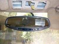
Mirror pinout
Follow Up Report:
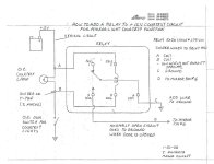
I contacted CIPA for the mirror pin out and they provided it. It was part of a schematic for installing the courtesy light to a +12v switch system. My plan was to hook this up but I recently decided to sell the 4Runner and leave it in India. As I mentioned on a previous post, I have to move back to the US for a year and I can't ship the vehicle. I decided to just buy a new (to me) car (most likely a 4th gen 4runner) and ship that to Turkey from the US.
Here's the pinout
Pin Function
1 Ignition controlled 12 volts
2 Ground
3 Reverse Autodimming Inhibit (optional use).
4 Temperature wire 1 (PN 36500 and 36501 only)
5 Temperature wire 2 (PN 36500 and 36501 only)
6 Ground when door is open for courtesy light function. (Optional)
7 jumper to Ignition controlled 12V (pin 1) or constant 12v if courtesy light function (pin 6) is connected.
CIPA support could not answer my questions about the type of terminal used in the connector for the mirror. I was hoping to buy some and connect up the courtesy light function (Pin 6) to the dome light so the map lights mirrored the dome light switch setting. I never looked at it so it may require a relay but I think you could get everything up in there without a problem. Pin 7 could be tapped into the factory map lights for the constant voltage. I finally found
this guy on ebay who sells
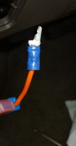
wire with the correct terminal. He sells it as power wire but obviously you could use it for anything.
I couldn't get the PDF to upload so here is the text from the instructions after I OCRed it:
PROCEDURE TO WIRE MIRROR TO FUNCTION AS COURTESY LAMPS
Applications: CIPA part numbers 36300, 36301, 36400, 36401, 36500, 36501
It is possible to connect mirror to your vehicle in a way that the map lamps will come on with the door courtesy lamps.
DOOR SWITCH CONNECTION
1. You will have to find the circuit that controls the door lamp function.
2. This circuit must go to ground when the door opens which is common on many cars but not all. My understanding is that the Corvette is positive 12 V when door is open. If courtesy lamp circuit is +12 Volts then a relay needs to be wired into the mirror harness.
3. A second power harness needs to be purchased (CIPA Part Number 36100WIRE).
4. The fused wire is stripped from the non fused ground wire. The ground lead is thrown away.
5. The fused lead is then tapped into the courtesy lamp control circuit using a wire T-Tap (Scotch Loc).
6. The wire is routed up around the instrument panel, up the ‘A’ pillar to the mirror.
7. The door control wire is connected to pin position 6 on the connector that plugs into the mirror.
The power harness, T-Tap and wire ties should be purchased through your local retailer or
CIPAUSA.com.
CIPA Part Number 36100WIRE contains:
1 Power Harness (Power and ground wires)
1 T-Tap
5 wire ties
[Note: Cipa sent me to Outdoor World to buy the 36100Wire part. It was $53. Stick with the eBay guy above]
We do not offer a ready made relay to make the mirror work with positive door switch systems.
Refer to form “How to add a relay to + 12 V courtesy circuit for mirror light courtesy function"
Pin Function
1 Ignition controlled 12 volts
2 Ground
3 Reverse Inhibit (optional use).
4 Temperature wire 1 (PN 36500 and 36501 only)
5 Temperature wire 2 (PN 36500 and 36501 only)
6 Ground when door is open. Door switch for courtesy light function. (Optional)
7 Ignition controlled 12 V or to battery if courtesy light function is desired.
POWER CONNECTION
Pin 7 needs to go to a constant 12 volt source to have the map lamps function in the courtesy mode when the ignition is turned off. The power harness that comes with your mirror kit has a jumper wire between pin 1 and pin 7 to reduce the number of standard hook ups required.
To wire pin 7 to constant 12 volts;
1. Obtain fused power wire PN 36100WIRE from CIPA.
2. Remove terminal from pin location 7 in the connector.
3. Tape over or cut off short jumper wire that goes from pin 1 to pin 7. Leave pin 1 connected to ignition controlled power source.
4. Locate a 12 volt constant power source. Best if power source is on the battery save circuit so if lights are left on they will shut off after 15 minutes when the car is not turned on.
5. The fused wire is stripped from the non fused ground wire. The ground lead is thrown away.
6. The fused lead is then tapped into the power circuit using a wire T-Tap (Scotch Loc).
7. Run the power wire from the source to the mirror following the other installed mirror wiring.
8. Insert the terminal into position 7 of the black connector.
9. Plug connector into mirror.
10. Test courtesy function of mirror.