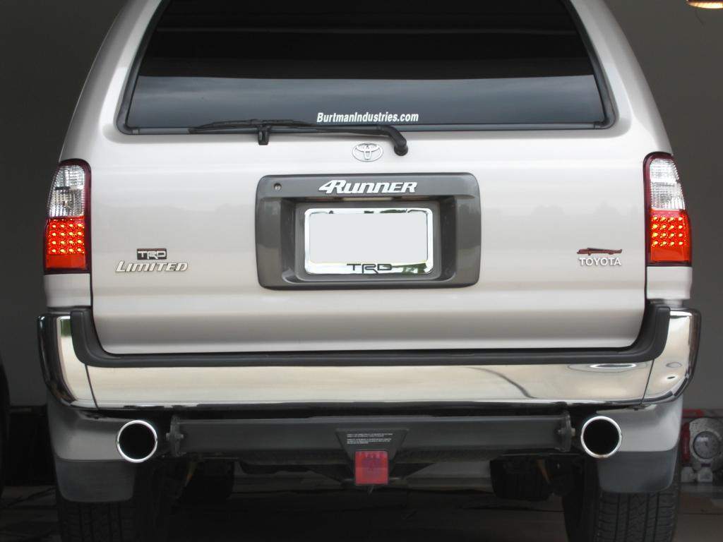
Crystal LED tails now available!

mikehinthehouse said:
hey Brian.. I see the tails on ebay but they all say for 01-02.. will they work on my 00???
mike
Yeah they will work on years, 96, 97, 98, 99, and 00 as well. The seller's are idiots.

maine runner said:
Fo -

Can you post a link or list the seller. I did a search and did not see them.

Thanks
When your searching, type in "4Runner LED" and you sould see them.
 
I'm pretty sure they do, I've seen them in the performance magazines for Tacoma's. Do a search on Ebay and type "Tacoma LED"
 
ABS light problem - WARNING for the record

I bought these tails, and love the look! The brake LEDs are BRIGHT! I went the route of pulling the side interior panels and plugging right into the wiring harness instead of splicing.

However, after installing these, the ABS light on my dash panel came on. I did my homework prior to buying the lights, and did not expect the problem on my vehicle, but others have also had this issue. Here's a thread over at Yotatech about it.

I wanted to make sure whether or not the ABS was working since the dash light was on, and my wife drives the truck with the kids a lot of the time. I found a good patch of gravel just outside my neighborhood, and slammed on the brakes at ~30 mph when I hit it. Slid all the way through it...

Thinking that all 4 wheels locking up might have fooled the system, I tried a few more times, braking at different points. Same result every time. Unfortunately, the system definitely does not function while the light is on.

To fix the problem, I needed some load resistors. I bought my load resistors from V-LEDs for a mere $14 shipped. I got them last Friday, and did some testing over the weekend.

It turns out that you only need to install ONE load resistor. The ABS light only comes on if both BRAKE lights are out. Very odd way to engineer it. I unhooked my LED tails and reconnected the stock housing to check this. The resistor needs to be connected between the ground wire and the BRAKE power wire, not the running lights, which is the wire that is referenced in the Yotatech thread (the brake wire is green with a silver stripe, and the running light is green with a white stripe).

Finally, the resistors I used are 50 Watt resistors, but in this application, we're only putting about 27 Watts of load through them (33 Watts at max), which is about the same power as the stock brake bulb. 27 Watts doesn't sound like much, but these resistors get VERY HOT!!! With the car running, I applied the brakes for 2 minutes, and then checked the temperature of the resistor I installed. I measured over 325 degrees F at the surface!!! Yikes!!! :bugeye:

That is more than hot enough to melt plastic, so be very careful where you install the resistors. I bolted mine to some of the car

 
Jason B said:
They are now on the site! I try to help out when I can, and I don't know how long I can keep this price going. I stand behind what i sell, so if you order, you will have peace of mind.

96-98 LED TAILS

99-00 LED TAILS

01-02 LED TAILS

4run_led_tail_96_02.jpg

This picture does not do these tails justice. These are super bright in person, look awesome, and are high quality.

I have these avail and finally got them installed on my own truck. They are awesome!
 
I personally wouldn't use resistors. Do it the right way and get an electronic flasher.

Too much of a chance for a fire.
 
Icepuck72 said:
I personally wouldn't use resistors. Do it the right way and get an electronic flasher.

Too much of a chance for a fire.

That's all fine and good, but the flasher unit only works for TURN SIGNALS! The BRAKE lights are what is causing the ABS light issue.

Please read more carefully next time instead of implying someone did a half-a$$ed job.

If you had read my post more carefully (and clicked the links), you would have seen the problem wasn't the turn signals. :mad:
 
Those look good. I might pick up a set if i get some birthday money. What was the difference between the one on the right and left? The right one doesn't look like it would fit a 3rd gen.

On a side note can anyone link me to the thread that explains how to change the third brake light to LED? You can PM me to avoid messing up this thread.

Thanks.
 
Last edited:
Clemsonfan15 said:
What was the difference between the one on the right and left? The left one doesn't look like it would fit a 3rd gen.

On a side note can anyone link me to the thread that explains how to change the third brake light to LED? You can PM me to avoid messing up this thread.

Thanks.

They are the same lights. The one of the left is a rear shot of the light itself. The one on the right has been rolled over on its side to show a shot of the side view.

LED 3rd Brake Light:
http://www.yotatech.com/f2/led-3rd-brake-light-3rd-gen-145628/
 
CO_FlyFisher, can you check the value of the resistors you used? Resistors shouldn't be measured in watts, they should be Ohms.

I'm interested in doing this, but want to know what to expect. And not start a fire ;):
 
They're 6 Ohm resistors. Click the link to V-Leds in my post above.

The only time they'll get really hot is if you're sitting on the brakes for a long time (like in a bad traffic jam). I haven't had any problems so far.
 
Thanks, and sorry, I should have clicked on the link.

I'm just curious though, is there a reason why you used those and not bigger resistors? Like even a 10 Ohm? A slightly bigger resistor should cut down the current/heat and I doubt adding 4 Ohms would dim the LED's much.

One last question, how did you wire the resistors in? I looked at that site, and they suggest putting the resistor in parallel to the brake line. This would most likely reduce the overall resistance of the load causing the current/heat to go up. Or did you wire yours in series?
 
Last edited:
I wired them in parallel. The LEDs hardly register (low resistance), so if you do the calculations, most of the current is going through the resistor. This is why you need to add resistance - if the CPU doesn't register the right resistance through the brake circuit (which, based on the 3rd brake light thread recently linked on yotatech, DOES include the third brake light), your ABS will be deactivated.

The reason for using 6 Ohm is that is the approximate equivalent of the actual brake bulb in the OEM application.

To figure out what to use, I ran the standard Ohm's law equation:
V = I * R
P = I * V -or- P = I^2 * R

I knew what the regular bulb was (27 Watts I think), so I just ran that backwards through the equation to figure out what resistance was needed (since V is known).

You might be able to get away with higher resistance (which wouldn't heat up as much), but I don't know. It probably depends on how the CPU calculates the total resistance. If it simply adds the resistance of the three lights together, higher resistance would likely work.
 
That seems strange to me. When 2 resistors are in parallel, the effective resistance of the circuit is lower than the smallest resistance.

Rt = (R1*R2) / (R1 + R2)

With a lower total resistance and assuming the voltage stays the same, you will actually draw more current (assuming you haven't reached the max current output). In my mind, assuming its a DC circuit, to replicate the load the resistor would have to be in series.

Anyway, I'm not trying to turn this into a circuits debate, what you have works for you, it just doesn't make sense to me. :)
 
I know - It's a little counter intuitive. You're making me actually think about this, and I'm starting to scratch my head. I don't have my books in front of me, but I'm thinking it has to do with using the chassis ground as a common point for ALL of the lights. I think each light's loop is esentially its own circuit. I would need to pull out the tester to verify this (and check the voltage drop across the resistor while I was at it). I've worked with LEDs a lot, so I don't know why I'm having such a hard time thinking about this application... :confused: :bonk:

Keep in mind the other half of the circuit is an arrangement of diodes (likely series-parallel), and maybe some matching resistors (I don't know - I haven't looked at the circuit board that closely). The diodes change the way the equations work a little. You can almost all but ignore them. They draw little current, and have almost no resistance.

My guess is that the diodes (likely Lumileds Superflux Orange-Red LEDs) are hooked up in 4 strings of 4 LEDs in series, and there are probably small matching resistors in each string.

I'll get back to you... :runaway:
 

Members online

Forum statistics

Threads
278,316
Messages
3,554,107
Members
248,016
Latest member
Advally Service

Trending content

Back
Top