Cymon's Weekend Warrior and MFD Thread

Attachments

  • IMG_5408.jpg
    IMG_5408.jpg
    132.1 KB · Views: 1,938
  • IMG_5409.jpg
    IMG_5409.jpg
    134.2 KB · Views: 1,945
  • IMG_5410.jpg
    IMG_5410.jpg
    131 KB · Views: 1,936
  • IMG_5411.jpg
    IMG_5411.jpg
    126.4 KB · Views: 1,940
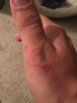
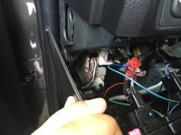
After doing the install originally this way, still having to reach up and behind the “Bolster Panel” and having my thumb look like the picture you see below (the plastic behind there is really sharp), I was told of an easier way by the one and only [MENTION=65614]Antman[/MENTION] . In a post a while ago showing after showing my finger carnage he very subtly in only a way he can do it told me there was an easier way (essentially calling me an idiot and that I was making it too hard on myself…lol).

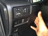
So here is the best way to access this area.

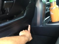
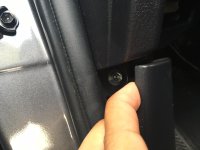
1. Reach next to the steering wheel
2. Pull Firmly
3. Panel comes unsnapped and you can access behind with no finger carnage.
 

Attachments

  • IMG_1073.jpg
    IMG_1073.jpg
    89 KB · Views: 1,913
  • IMG_5412.jpg
    IMG_5412.jpg
    125.7 KB · Views: 1,899
  • IMG_5413.jpg
    IMG_5413.jpg
    127.2 KB · Views: 1,943
Last edited:
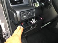
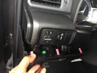
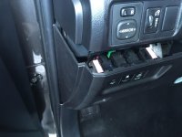
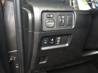
Next reach behind and push the tab that releases the factory blank switch and push it out to the front.


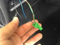
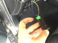
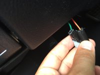
Now as I had already installed this and just went back and put the blank back in to show how I did it, the wires from the AOB switch were already inside. Below is a picture of them. The green plug just snaps right back into the back of the AOB replacement switch (plug and play).
 

Attachments

  • IMG_5415.jpg
    IMG_5415.jpg
    132.3 KB · Views: 1,947
  • IMG_5416.jpg
    IMG_5416.jpg
    126.2 KB · Views: 1,929
  • IMG_5417.jpg
    IMG_5417.jpg
    123.7 KB · Views: 1,912
Then using a couple of wire-taps (I know this may not be the best way, but is the easiest and I will explain in my summary) I connected the AOB switch to the “Wiper-De-Icer Switch” This connects the AOB switch to the lighting circuit, illuminating it with the other factory switches and allowing for dimming. I used the wiring diagram and explanation by [MENTION=103267]Saker[/MENTION] in his thread I posted above.

AOB Blue -> Factory Green
AOB Black -> Factory Grey
 

Attachments

  • IMG_5418.jpg
    IMG_5418.jpg
    122.2 KB · Views: 1,936
  • IMG_5419.jpg
    IMG_5419.jpg
    134.6 KB · Views: 1,931
  • IMG_5420.jpg
    IMG_5420.jpg
    125.4 KB · Views: 1,915
  • IMG_5421.jpg
    IMG_5421.jpg
    128.7 KB · Views: 1,912
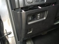
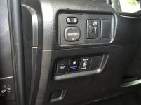
I then pushed my new switch (AOB switch) into the knockout hole (it clicks right in place) and then attached the green plug into the back of the AOB Switch. At this point two of the AOB wires, the green and red, are still unattached, as they will control my light bar that I hopefully will be getting later this week. I just taped them and stored them behind the dash panel.
 

Attachments

  • IMG_5422.jpg
    IMG_5422.jpg
    131.9 KB · Views: 1,893
  • IMG_5423.jpg
    IMG_5423.jpg
    132.8 KB · Views: 1,893
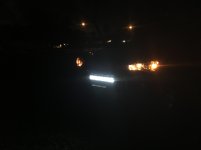
Final Pics: As you can see (well actually you can't, because these pictures were taken during the day...just trust me) the switch illuminates and dims.

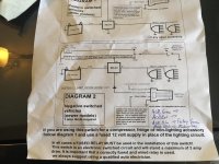
And the Wiring Diagram from AOB I forgot to post before.
 

Attachments

  • IMG_5424.jpg
    IMG_5424.jpg
    134 KB · Views: 2,002
  • IMG_5425.jpg
    IMG_5425.jpg
    132.4 KB · Views: 2,031
  • IMG_5426.jpg
    IMG_5426.jpg
    135.2 KB · Views: 2,317
Summary:

Hopefully you can see that this is a pretty straightforward process with the right planning and prior knowledge. I strongly suggest anyone attempting this to read through [MENTION=83083]rigtec[/MENTION] post “To Switch or Not to Switch”, which I will link again here…

http://www.toyota-4runner.org/5th-gen-t4rs/192198-switch-not-switch.html

This is the reason I attached the AOB switch to the “Wiper De-Icer” switch and not directly to the dimmer.

Now why did I use wire taps? Because it’s easier! I completely understand it is not the best way. I do not own a soldering kit, and have never done it before so I didn’t feel comfortable although this is the best way to connect. I also didn’t feel like splicing, although I do know how to do it. In the end wire taps may not be the most secure, but they are inexpensive and easy to install, so if I see intermittent power in the future I can always reattach new. Knock on wood; I have had no issues so far in the 3 months they have been connected this way.

As to why the “Sasquatch Light”? Well that is a joke that goes back to when I was teaching in Maryland. I used to run the Outdoor Education program at our school, where I would take 200+ students and chaperones to the mountains in Western Maryland and do team building and outdoor activities (canoeing, camping, hiking, team-building etc.). Our orienteering course needed a little sprucing up, and it was about the time that “Finding Bigfoot” began appearing on T.V. So we aligned orienteering with “Going Squatching”. We made “squatch knockers” and did the silly calls and everything else (even got hats for the teachers). So when I saw this switch I had to have it. It would have been great in Maryland or NorCal, but they don’t make a “Swamp Ape” or “Skunk Ape” switch, which is what they call it down here in Florida so Sasquatch will have to do.

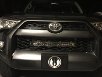
Stay Tuned for the final part of this mod, the “If I Can Do It You Can” behind the grill LED light bar install…

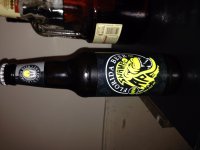
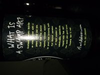
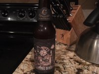
Oh and the beer of choice for this install…

 

Attachments

  • IMG_5427.jpg
    IMG_5427.jpg
    135.6 KB · Views: 1,924
  • IMG_3393.jpg
    IMG_3393.jpg
    112.4 KB · Views: 1,948
  • IMG_3394.jpg
    IMG_3394.jpg
    130 KB · Views: 1,947
Last edited:
Now why did I use wire taps? Because it’s easier! I completely understand it is not the best way. I do not own a soldering kit, and have never done it before so I didn’t feel comfortable although this is the best way to connect. I also didn’t feel like splicing, although I do know how to do it. In the end wire taps may not be the most secure, but they are inexpensive and easy to install, so if I see intermittent power in the future I can always reattach new. Knock on wood; I have had no issues so far in the 3 months they have been connected this way.

Sorry man, when I see wire taps......it's like running fingernails down a chalk board for me..........lol.

As to why the “Sasquatch Light”? Well that is a joke that goes back to when I was teaching in Maryland. I used to run the Outdoor Education program at our school, where I would take 200+ students and chaperones to the mountains in Western Maryland and do team building and outdoor activities (canoeing, camping, hiking, team-building etc.). Our orienteering course needed a little sprucing up, and it was about the time that “Finding Bigfoot” began appearing on T.V. So we aligned orienteering with “Going Squatching”. We made “squatch knockers” and did the silly calls and everything else (even got hats for the teachers). So when I saw this switch I had to have it. It would have been great in Maryland or NorCal, but they don’t make a “Swamp Ape” or “Skunk Ape” switch, which is what they call it down here in Florida so Sasquatch will have to do.

Stay Tuned for the final part of this mod, the “If I Can Do It You Can” behind the grill LED light bar install…

Oh and the beer of choice for this install…

Cool story and great write-up! :cheers:
 
Sorry man, when I see wire taps......it's like running fingernails down a chalk board for me..........lol.

I'm sure...lol! I may go back and eventually do a true splice if I start not getting a strong enough or intermittent current.

Thanks again for all of the great info!
 
Armor

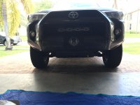
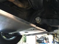
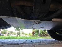
So I mentioned in my light bar install that it would be my last mod for a while unless I somehow came by a great deal on armor. I realized I needed an upgrade since I don't have plans for a lift anytime soon, and my stock skids go beat to hell when I took the 101 course up a Rausch Creek.

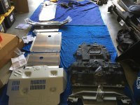
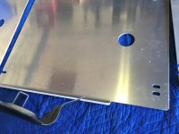
Well a couple of weeks ago I lucked into a great deal from another member on this site who was offloading some of his things because of a move (it was so good even my wife said I would be an idiot if I didn't buy it). A 4 hour drive each way later and I had a brand new set of Aluminum RCI skids (also including a steel rear differential skid) and sliders. They guy I was buying them from had a TRD pro, so all I had to buy was the TRD skid from an online dealer to complete the set.

Not going to do a full write-up because honestly the install is about as straightforward as you can get. Just line it up and bolt them on (plus they come with instructions, except the sliders). The skids took me about 4 hours, but that was mainly due to me doing it by myself, with only my bottle jack and some jack stands. If I had a couple of ramps it would have been a lot easier.

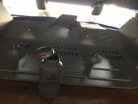
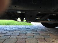
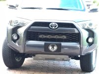
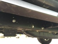
Here are the skids install pics. I've installed everything so far except the gas tank skid and rear differential (ran out of time last weekend). As you can see, they are a huge improvement over the stock skids both in area of protection and strength/thickness.

One final note is because they are aluminum I only had a net game of about 50 lbs total by adding the full skid package. When you pair that with the sliders (42 lbs a piece) I have a well protected rig and have only added a total of about 140 lbs of weight (like having an extra person in my third row).
 

Attachments

  • IMG_5779.jpg
    IMG_5779.jpg
    126.3 KB · Views: 1,824
  • IMG_5780.jpg
    IMG_5780.jpg
    135.3 KB · Views: 1,753
  • IMG_5781.jpg
    IMG_5781.jpg
    129.8 KB · Views: 1,806
  • IMG_5782.jpg
    IMG_5782.jpg
    135 KB · Views: 1,794
  • IMG_5784.jpg
    IMG_5784.jpg
    124 KB · Views: 1,795
  • IMG_5785.jpg
    IMG_5785.jpg
    133.1 KB · Views: 1,815
  • IMG_5786.jpg
    IMG_5786.jpg
    136.3 KB · Views: 1,782
  • IMG_5787.jpg
    IMG_5787.jpg
    118.3 KB · Views: 1,812
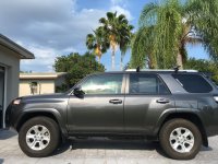
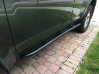
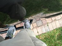
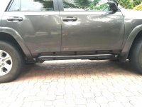
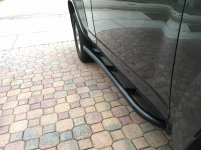
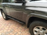
The RCI sliders where not really on my radar until I got this deal. I was really looking for more of a "step" slider (like the hefty fab, shrockworks or C4) to eventually replace my "Rigid Running Boards". So far I am very pleasantly surprised with the RCI. They are beefier than I thought, super easy to install (complete bolt on with no u-bolts, stick nuts, drilling or any other modifications...just line up the holes and screw the bolt in). They also function better as a step for my size 12's then I expected (and they have been approved by my 4 year old daughter).

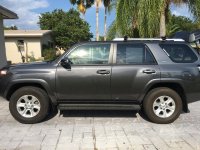
Before pic and some after install...followed by what it looked like with the running boards on.
 

Attachments

  • IMG_4775.jpg
    IMG_4775.jpg
    137.8 KB · Views: 1,767
  • IMG_5795.jpg
    IMG_5795.jpg
    123.8 KB · Views: 1,794
  • IMG_5796.jpg
    IMG_5796.jpg
    136.7 KB · Views: 1,753
  • IMG_5797.jpg
    IMG_5797.jpg
    130.7 KB · Views: 1,791
  • IMG_5798.jpg
    IMG_5798.jpg
    126.6 KB · Views: 1,813
  • IMG_5799.jpg
    IMG_5799.jpg
    134.5 KB · Views: 1,799
  • IMG_5800.jpg
    IMG_5800.jpg
    134.7 KB · Views: 1,802
  • IMG_4774.jpg
    IMG_4774.jpg
    139.1 KB · Views: 1,743
Last edited:
Of course I finished off the install with a local IPA...
 

Attachments

  • IMG_5788.jpg
    IMG_5788.jpg
    129.8 KB · Views: 1,776
[MENTION=120701]Cymon[/MENTION],

Send me a large green coconut from that tree! :becky:

LOL...I'd fedex one to you, unfortunately for you we just moved out and into our new house last week. No coconut, mango, or avocado trees at this one.
 

Members online

Forum statistics

Threads
278,312
Messages
3,554,089
Members
248,016
Latest member
Advally Service

Trending content

Back
Top