DIY Tire Carrier

chris.817

Junior Member
Hey folks,

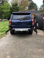
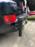
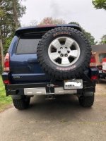
Just finished this build and thought I'd share. First, thanks go out to Adventurous Mind on YouTube for the inspiration. I sourced parts from his links and also re-designed based on his complaints on his build. Sorry, no fancy video, just pictures.

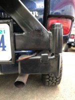
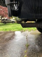
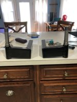
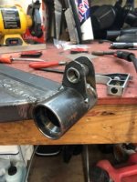
The complaints I addressed were the through bumper mount and the too thin metal used for the center support. This version goes straight through the bumper so it can be installed and removed with the bumper in place. It bolts directly to the chassis and I sleeved the tubing so it would not crush. I have not decided on what to put on the driver's side at this point so it is unused. My lesson learned would be to mount the tire to the plate and weld on the lug bolts versus drilling and pressing them in. They do not line up well enough for the sleeved lug nuts. Also, I only used one latch. Seemed plenty.

After a couple days of using it I can say that it is rock solid. It has not been off road but I don't anticipate issues. Fingers crossed.
 

Attachments

  • IMG_2810 sm.jpg
    IMG_2810 sm.jpg
    63.3 KB · Views: 1,093
  • IMG_2812 sm.jpg
    IMG_2812 sm.jpg
    49.8 KB · Views: 1,035
  • IMG_2813 sm.jpg
    IMG_2813 sm.jpg
    37.7 KB · Views: 1,038
  • IMG_2814 sm.jpg
    IMG_2814 sm.jpg
    42.4 KB · Views: 1,022
  • IMG_2815 sm.jpg
    IMG_2815 sm.jpg
    48.6 KB · Views: 1,031
Register to hide this ad
Nice! I have a double shear mount sitting in my garage waiting for some time to do just this! Do you have a picture of how it mounts to the frame? I had considered just welding it on, but if it's pretty solid just bolted on...
 
Don't weld it on...

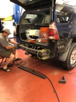
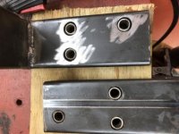
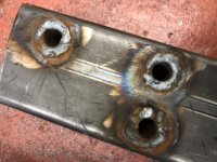
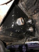
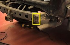
I sleeved and boxed the tubing. I welded 1/2" nuts to a backing plate, cut the cap off the chassis (see yellow), welded in the backing plate, then welded the chassis cap back on. My buddy is holding one in place. The extensions then bolt to these nuts through holes drilled in the chassis. This makes the extensions removable which they certainly need to be so the bumper can be removed in the future.

I'm pretty sure these could double as tow points. And please no welding jokes... I'm learning.
 

Attachments

  • IMG_2732 sm.jpg
    IMG_2732 sm.jpg
    65 KB · Views: 1,008
  • IMG_2738 sm.jpg
    IMG_2738 sm.jpg
    34.6 KB · Views: 998
  • IMG_2739 sm.jpg
    IMG_2739 sm.jpg
    40.1 KB · Views: 990
  • IMG_2751 sm.jpg
    IMG_2751 sm.jpg
    51.9 KB · Views: 1,001
  • IMG_2817 sm.jpg
    IMG_2817 sm.jpg
    32.8 KB · Views: 1,001
Last edited:
Wow, that looks great.

I would consider buying that if you were producing them. Hint Hint
 
I sleeved and boxed the tubing. I welded 1/2" nuts to a backing plate, cut the cap off the chassis (see yellow), welded in the backing plate, then welded the chassis cap back on. My buddy is holding one in place. The extensions then bolt to these nuts through holes drilled in the chassis. This makes the extensions removable which they certainly need to be so the bumper can be removed in the future.

I'm pretty sure these could double as tow points. And please no welding jokes... I'm learning.

Awesome...thanks for the info. The thought had crossed my mind that I didn't want two huge slits going up through the bumper. I will definitely dip into your design a little bit to add on to what I had in mind.

Ha, I don't expect near that level of welds, it will be my first time, learning from a friend. :bravo:

Happy to see a few more posts of this kind of stuff, I don't want/need a full steel rear bumper, and the Wilco is way overpriced and bulky IMO, along with taking up the hitch. This type of carrier seems to be easy enough and fits my criteria. Good job again :thumb:
 
Great job and excellent idea! You could totally manufacture this and sell it!

Do you have a closeup of the locking pin assembly?
 
Locking pin

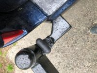
The locking pins are two piece. The pin/handle/spring and the threaded sleeve.
First picture is the sleeve tacked to mounts I built. I added a ramp for them to lock into in second picture (also shows boxed end and corner gusset). Third picture is finished product. I can release them for full open.
 

Attachments

  • IMG_2781 sm.jpg
    IMG_2781 sm.jpg
    61.5 KB · Views: 973
  • IMG_2786 sm cropped ramp.jpg
    IMG_2786 sm cropped ramp.jpg
    27.2 KB · Views: 957
  • IMG_2811 sm.jpg
    IMG_2811 sm.jpg
    65.3 KB · Views: 997
Some assembly required

Folks,

I did this project because I didn't want to spend the money on a bumper and all the accessories. They are very nice but cost as much as I paid for the vehicle... I also thought I could give back here by providing the process I followed based originally off the one I found on youtube. I can provide all the measurements to save you a lot of time, trial and error. I'm not a fabricator nor is this kind of stuff a business for me.

All that said, I'm willing to duplicate it for someone. There are two catches.

First, it does require welding on the chassis to access the inside of the boxed frame to insert the backing plate and nuts. I don't see any way around it. See picture of corner that must be removed and re-welded. It's no big deal but has to be done.

Second, the center brace was fabricated on the vehicle to match the supports with the weight of the tire in place. I don't believe that's a show stopper but would have to test a theory to be sure.

If anyone is really serious and wants to be a test case, just PM me. We can see if I can do it for a price that's reasonable.

Thanks again for all the positive feedback. I really appreciate it.

Stay tuned for the winch mount...

Chris
 

Attachments

  • IMG_2732 crop.jpg
    IMG_2732 crop.jpg
    43.2 KB · Views: 874
Last edited:
Folks,

I did this project because I didn't want to spend the money on a bumper and all the accessories. They are very nice but cost as much as I paid for the vehicle... I also thought I could give back here by providing the process I followed based originally off the one I found on youtube. I can provide all the measurements to save you a lot of time, trial and error. I'm not a fabricator nor is this kind of stuff a business for me.

All that said, I'm willing to duplicate it for someone. There are two catches.

First, it does require welding on the chassis to access the inside of the boxed frame to insert the backing plate and nuts. I don't see any way around it. See picture of corner that must be removed and re-welded. It's no big deal but has to be done.

Second, the center brace was fabricated on the vehicle to match the supports with the weight of the tire in place. I don't believe that's a show stopper but would have to test a theory to be sure.

If anyone is really serious and wants to be a test case, just PM me. We can see if I can do it for a price that's reasonable.

Thanks again for all the positive feedback. I really appreciate it.

Stay tuned for the winch mount...

Chris

Just wondering where abouts are you located ?
 
What dimensions did you end up going with on the arms that attach to the frame? What size tubing did you go with?
 
Man I would love to have the blueprints of this project and do it myself. This is something I've been searching for!

Sent from my SM-N975U1 using Tapatalk
 

Members online

Forum statistics

Threads
278,309
Messages
3,554,068
Members
248,016
Latest member
Advally Service

Trending content

Back
Top