Electricians-Get in here (Wiring Diagram)

domstriker

New member
I'm installing a cooling fan using a relay and just a dash rocker switch. I'm not installing a thermo switch or sensor. I've been searching for wiring diagrams and can't find one without a sensor or themo switch.

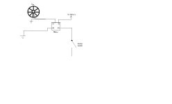
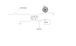
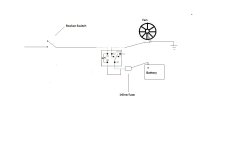
Take a look at the below diagrams. Should I wire it like the first diagram and put my rocker switch where the temp switch is labeled? Or should I wire it like the bottom diagram? I'm going to wire an inline fuse in between the battery and relay in either scenario.

Fan_relay.jpg
 

Attachments

  • wiring.jpg
    wiring.jpg
    33 KB · Views: 7,399
Last edited:
Register to hide this ad
Diagram 1 won't work because there is no ground for the switch. Diagram 2 would work as long as the rocker switch has a power supply. Is the objective to have a manually controlled cooling fan? Or a cooling fan temperature regulated with a manual override? Or neither :biggrin2:
 
Diagram 1 won't work because there is no ground for the switch. Diagram 2 would work as long as the rocker switch has a power supply. Is the objective to have a manually controlled cooling fan? Or a cooling fan temperature regulated with a manual override? Or neither :biggrin2:

The objective is to have a manually controlled cooling fan with NO thermo control switch.

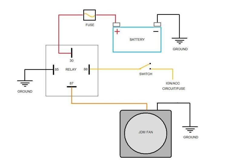
How does this look? Assume switch is grounded.
 

Attachments

  • Wiring Updated.jpg
    Wiring Updated.jpg
    41.3 KB · Views: 16,974
The difference is just if you want to switch the positive lead to the relay's coil or the negative lead. If you switch the positive lead then you can use your ACC circuit to drive the coil, which means your fan would only work when your key is in the ignition and in the acc or run position. If you switch the negative lead as shown then your fan could be turned on any time, even if the key is not in the truck.

In general I like to switch the positive lead for consistency, and because you can then ground directly to a chassis point. As an added benefit if you get a short on the coil circuit the worst thing that can happen is you blow the fuse, if you switch the ground and get a short you could wind up with your fan stuck in the on position if the ground shorts out before the switch.

- Matt
 
So I wired it all together using the diagram in post #4. Everything works fine when using an OEM Toyota fog light rocker switch. Switch turns it on and off w/o key turned on. This is what I wanted.

I also tried it with a three prong switch with an LED. I can't figure out how to wire this particular switch. It would be pretty cool if I could get the light to work on the switch as well.
 
thermo control could save your bacon

dom-my only comment would be that thermo controlled is not necessarily a bad thing. It's easy to get distracted and then the thermo control can kick in to save your hide if you get my drift.

I always thought the point of the switch was to control the fan when you do not want it kicking on-like for a water crossing. In other words you can always have it "on" that is the thermo control is ruling the show-except when you want it off. You don't want it spraying your engine compartment at an inopportune time like a water crossing. Or as a safety measure when the truck is being worked on...

3 prong switch as alluded to is power/ground/output to device-simply avoiding the ground disables the lamp at the switch but still allows it to work. A simple fog light schematic of your same switch would probably illuminate (aha a pun) you further on which prong is which. With it always on-you might actually prefer not to have the lamp lit at all times-but perhaps only when parking lights are on.
 
dom-my only comment would be that thermo controlled is not necessarily a bad thing. It's easy to get distracted and then the thermo control can kick in to save your hide if you get my drift.

I always thought the point of the switch was to control the fan when you do not want it kicking on-like for a water crossing. In other words you can always have it "on" that is the thermo control is ruling the show-except when you want it off. You don't want it spraying your engine compartment at an inopportune time like a water crossing. Or as a safety measure when the truck is being worked on...

3 prong switch as alluded to is power/ground/output to device-simply avoiding the ground disables the lamp at the switch but still allows it to work. A simple fog light schematic of your same switch would probably illuminate (aha a pun) you further on which prong is which. With it always on-you might actually prefer not to have the lamp lit at all times-but perhaps only when parking lights are on.

The only time I need the fan is driving up mountain passes or driving slowly uphill.

I'm not sure the fan is going to do much. I'll keep everyone posted on my observations in a separate post.

The switch is still giving me trouble. I can wire it so the led works as it's switched on but the fan won't activate. I can wire it so the switch works but the led doesn't activate. I can't figure out how to wire it so the light works and the fan works. It got too dark so I'll have to figure it out tomorrow. Days sure are getting shorter already.
 
The only time I need the fan is driving up mountain passes or driving slowly uphill.

I'm not sure the fan is going to do much. I'll keep everyone posted on my observations in a separate post.

The switch is still giving me trouble. I can wire it so the led works as it's switched on but the fan won't activate. I can wire it so the switch works but the led doesn't activate. I can't figure out how to wire it so the light works and the fan works. It got too dark so I'll have to figure it out tomorrow. Days sure are getting shorter already.

It may not be possible if you are switching negative. AFAIK, LED's have to be wired for correct polarity, and those switches are made assuming you are switching positive. If you went with diagram #5, it would be probably be no problem. I can't think of a way to wire those things backwards, so to speak, to get the LED working that keeps the switch working if you are switching negative. But someone may be smarter than I am.
 
It may not be possible if you are switching negative. AFAIK, LED's have to be wired for correct polarity, and those switches are made assuming you are switching positive. If you went with diagram #5, it would be probably be no problem. I can't think of a way to wire those things backwards, so to speak, to get the LED working that keeps the switch working if you are switching negative. But someone may be smarter than I am.

Sorry, I'm not an electrician. I don't know what "switching negative" means.

The reason I didn't go with something like diagram #5 is I don't know where to hook up to ACC power.
 
Sorry, I'm not an electrician. I don't know what "switching negative" means.

The reason I didn't go with something like diagram #5 is I don't know where to hook up to ACC power.

You have the switch on the ground leg (or negative side) of the coil. In #5, the switch takes positive from the ACC circuit and the other side of the coil goes direct to ground (negative).

I think you either have to install the switch so it is on the wire connecting the coil to the positive voltage (i.e. indirectly to the Batt Positive terminal) or somehow access LED connections inside the switch and turn them around so the polarity is correct. I assume the second option is physically impossible to achieve.

The audio HU is usually a good place to get ACC power(red or yellow, I forget which). Or even the silly clock that doesn't work can be a good place. One of the leads is ACC so it knows when to power the numbers that don't light up anymore. The relay coil is not enough to overload either circuit.

Maybe there is an LED switch out there made to work on the ground leg, but I have never seen one on the rack. I never really looked for one. Toyota wires a lot of things with switched negatives so a stock switch might even work, although cost and label are issues. A non-LED illuminated switch that does not care about polarity is another option. They are clunky but they are out there. (It can't be one that grounds through the case, however.)

I am not an expert on LED although I have installed several of these switches. I just don't want you to beat yourself up attempting the impossible.
 
Last edited:
You have the switch on the ground leg (or negative side) of the coil. In #5, the switch takes positive from the ACC circuit and the other side of the coil goes direct to ground (negative).

I think you either have to install the switch so it is on the wire connecting the coil to the positive voltage (i.e. indirectly to the Batt Positive terminal) or somehow access LED connections inside the switch and turn them around so the polarity is correct. I assume the second option is physically impossible to achieve.

The audio HU is usually a good place to get ACC power(red or yellow, I forget which). Or even the silly clock that doesn't work can be a good place. One of the leads is ACC so it knows when to power the numbers that don't light up anymore. The relay coil is not enough to overload either circuit.

Maybe there is an LED switch out there made to work on the ground leg, but I have never seen one on the rack. I never really looked for one. Toyota wires a lot of things with switched negatives so a stock switch might even work, although cost and label are issues. A non-LED illuminated switch that does not care about polarity is another option. They are clunky but they are out there. (It can't be one that grounds through the case, however.)

I am not an expert on LED although I have installed several of these switches. I just don't want you to beat yourself up attempting the impossible.

What you're saying makes sense. I was pulling my hair out as the sun was going down yesterday. Thanks for the info.

So can I just switch the wires on 85 and 86 under my current configuration and be "switching positive" without hooking up to ACC/IGN?
 
Last edited:
No, you are just switching ends of the coil. A coil doesn't care about polarity just like an incandescent bulb. It's the LED in the switch that cares. You need to move the switch to between the battery power (either direct to the Batt 12V + or via ACC) and the coil and connect the other end of the relay coil directly to ground.
 
Last edited:

Members online

Forum statistics

Threads
278,316
Messages
3,554,108
Members
248,016
Latest member
Advally Service

Trending content

Back
Top