Fuel Tank Relocation (and new Rear Bumper design)

Ok anybody want to tell me why photos won’t work? I’ve edited this like 4 times.
Edit for the 15th time. Got the photos in here but damn that was a PITA on mobile.


For those of you considering the dual tank option I thought I’d share.

49558778227_467c4f76d8_n.jpg

49558777892_63f1afd921_n.jpg

The divider inside allows the nozzle to be pushed into either the front or rear tank and will auto stop when full. Also works with our people’s republic of California bs where an extra dome light is illegal.

49558086248_b928e9ac0d_n.jpg

I did have to widen the opening for the nozzle using my die grinder.

49558777887_7fbe50dcc9_n.jpg

49558045983_9c5bb03fa4_n.jpg

Completely fits under the factory cover. I’ll finish the pump tie in and wiring this weekend hopefully and show that. I decided to go with check valves and that sender signal converter to run both tanks on one switch with the factory gauge.
 
Last edited:
Ok anybody want to tell me why photos won’t work? I’ve edited this like 4 times.

For those of you considering the dual tank option I thought I’d share this.

2ivkG4N

2ivkGaz


The divider inside allows the nozzle to be pushed into either the front or rear tank and will auto stop when full. Also works with our people’s republic of California bs where an extra dome light is illegal.

2ivh9sU


I did have to widen the opening for the nozzle using my die grinder.

2ivgWuF

2ivkFZE


Completely fits under the factory cover. I’ll finish the pump tie in and wiring this weekend hopefully and show that. I decided to go with check valves and that sender signal converter to run both tanks on one switch with the factory gauge.

Cool idea. So you fill one tank, it autostops, then you pull the nozzle out and jam it in the other "side" of the filler neck to fill the second tank?

Did you choose the geometry of the neck for any reason other than if fits like that?

I think you've grabbed the wrong type of
share link from flickr. I was able to right click > view image and see the pics on flickr. Your image URL should end in ".jpg" or ".jpeg" or gif or whatever.
 
Finally getting around to doing this. Just throwing a question out there. Are most people running an aftermarket gauge? Or has anyone tried the Classic instruments fuel link module or the Tanks Inc metermatch module? The reason I’m asking is I want to use the OE gauge and wanted as clean an install as possible. I first thought I’d follow in [MENTION=118207]midcoma[/MENTION]’s footsteps and heavily modify the tank to fit the Toyota sending unit. Then I saw these modules. The wiring diagram is so damn easy and setting up the gauge also looks fairly easy too. I ordered the Tanks Inc module and will do a write up and review if people want it. The reason I went with the tanks inc one is because it’s $69 compared to $120 for the CI one.

Links to the stuff:

MeterMatch Fuel Gauge Interface Module
Classic Instruments SN34 Fuel Link Interface
 
Last edited:
Actually wiring up the classic instruments this week/weekend since I got all the plumbing finished up. Plan is to run the necessary signals through a DPDT switch and a 25A DPDT relay. Just need to research tying into the low fuel light.

For those interested in the plumbing I went with a couple check valves and a single switched return line so if it has an electrical issue it will default to oem Toyota.

49586888767_81d08b866b_w.jpg


49586888752_74d7983be7_w.jpg


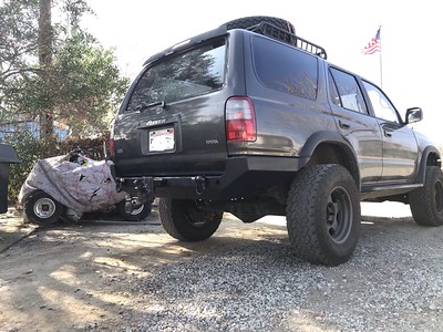
And just because I’ve never posted the 4Runner before. Here it is, it has an old thread from a previous owner a few people before me.

49586966452_ae932d204d_w.jpg


49586640886_c67b121e45_w.jpg
 
Last edited:
Actually wiring up the classic instruments this week/weekend since I got all the plumbing finished up. Plan is to run the necessary signals through a DPDT switch and a 25A DPDT relay. Just need to research tying into the low fuel light.

For those interested in the plumbing I went with a couple check valves and a single switched return line so if it has an electrical issue it will default to oem Toyota.

I was trying to figure out the low fuel light too. Instead of using the Toyota one I think I’m gonna pull the bulb from the dash and wire in a mini led alarm light
 
Sounds like a good idea but if it buzzes I’d want to silence it. I’ve been on a trail or two with empty jerry cans and a nearly empty tank, a buzz probably would not have helped the anxiety.

As far as the light... I need to pull up the diagram again to confirm but I believe the factory light is simply a resistive circuit that is completed when the ohms of the sender are below or above a certain point. If that’s the case the classic instruments should naturally set it off. But, the classic instruments device also has a low fuel light output built in if that’s not the case. So it may be very easy to enable.
 
Sounds like a good idea but if it buzzes I’d want to silence it. I’ve been on a trail or two with empty jerry cans and a nearly empty tank, a buzz probably would not have helped the anxiety.

As far as the light... I need to pull up the diagram again to confirm but I believe the factory light is simply a resistive circuit that is completed when the ohms of the sender are below or above a certain point. If that’s the case the classic instruments should naturally set it off. But, the classic instruments device also has a low fuel light output built in if that’s not the case. So it may be very easy to enable.

The aftermarket warning light doesn’t buzz or make noise. They’re just called an alarm light. I guess indicator light is the better name
 
Is the low fuel light connected to the gauge level or is it a separate system in the tank? I am inclined to believe it's connected to the gauge level because my fuel light used to "crash" where it would drop to empty and the low fuel light would flash (even if the tank were full).

...oddly enough the gauge magically fixed itself, it used to "crash" every day, but it hasn't done that now for months.
 
This is the fuel gauge calibrator I'm using. With a aftermarket floatless fuel level sender.

Speedway Fuel Level Gauge Sending Unit Interface Module

Pricy at 104 but it has a warning light built in that turns on at 15% fuel level. It needs a led bulb and that is a easy swap. Last of the tank filler neck parts should be in later this week, then its install time.

I saw that one too. Looks like we have 3 people trying out all 3 options. We should all give reviews after awhile. They seem to all be very similar with minor differences in how they are calibrated. I’ve gone through all of the instructions online and each seem simple. Might just come down to personal preference
 
haven't checked in here in a bit, but pretty excited to see these modules.

I'm thinking about a mounting solution under the factory fuel pump access plate... seems a logical place to tie in the tank & factory wiring at first glance, and reasonably accessible.
 
Is the low fuel light connected to the gauge level or is it a separate system in the tank? I am inclined to believe it's connected to the gauge level because my fuel light used to "crash" where it would drop to empty and the low fuel light would flash (even if the tank were full).

...oddly enough the gauge magically fixed itself, it used to "crash" every day, but it hasn't done that now for months.
It is different depending on year. The early trucks have a separate thermistor that turns on the low-fuel light, the later trucks have it integrated into the gauge cluster. I believe the cutoff for that change is the 98/99 mid-cycle refresh.

-Charlie
 
I'm thinking about a mounting solution under the factory fuel pump access plate...

Holy crap there’s an access plate?! I haven’t had to do the 4runner fuel pump yet. I’m too used to ford, and dropping the tank, eat shit ford!!

Anyway, I mounted my sender unit under the dash on an angled plate and the switching relay is beneath the center console where my e-locker relay is as well.
 
Its done and runs, it can be switched while running, and the factory gauge is functional. However; the low fuel light is not.

The heavy load is done by a 25A DPDT relay mounted under the center console and wiring is routed into the cab attached to the parking break cable. It is used to switch between the pumps and a selector valve on the return lines. Feed lines have high flow check valves so no electronics are necessary
49607155351_2fc7362427_w.jpg


and the classic instruments sender unit under the dash, just above the OBDII port, in a semi accessible location for calibration.
49607404172_63fc6a2787_w.jpg

49606649663_8547a7e031_w.jpg


As calibrations go, there was a slight learning curve to how to do it and unfortunately if you don't get it correct the first time around you have to start all over which was tedious. My second trip around the block and I got it figured out. You also need to be able to see the gauge while holding the button for calibrations. There is a preset for the ford sender which eliminates the first half of the setup process so ultimately I was only calibrating what it sends to my Toyota gauge.

Switching is done on a DPDT switch with one pole feeding the 25A relay coil and the other switching between the sender signal from each tank and going to the gauge.
49606649453_50569ec771_w.jpg


The small switch on top is unrelated, its for switching Abs on and off.

As far as the low fuel light; the factory wiring for the instrument cluster uses resistance to ground in the factory sending unit to turn it on. The classic instruments device provides for both a switched ground or switched hot low level light but when the ground is used it seemed to create a feed back when the ford tank read as empty that drastically affected it running on the factory Toyota system. So for now I don't have a low fuel light associated with the auxiliary tank. I did however extend the wire for the factory light down under the knee panel so I can experiment more later.

The wire from the sender to the gauge is yellow/red and the wire for the low fuel light is black/red.

attached is the instrument cluster wiring diagram for those looking to integrate but note!!!!!
THE THREE PLUG LETTERS DID NOT MATCH MY INSTRUMENT CLUSTER. They were the opposite A=C, B=B, C=A. Confirm by looking at multiple wire colors and their positions as well as the number of pins for each plug. There is a yellow/red wire on both plug A and C. (ask me how I learned)
 

Attachments

What part of Southern California are you in? I’m In San Diego for work this week.

What year is your 4Runner? The wiring did change throughout the years. I have the PDF FSM for a 2000. If you want to meet up I can save you a copy if it would be useful.
 
What part of Southern California are you in? I’m In San Diego for work this week.

Thanks for the offer, Id certainly be interested. If not for the wiring then for the 90% of the rest of them that are the same. You never know when you'll need data like that. Im in Redlands California about ~1.5hrs north of San Diego and inland from the coast.

Mine is a 97 and I know there was a pretty significant change in wiring that occurred between 97-98. A while back I was looking into swapping a 98 MT into a 97 AT for a friend and it just looked like more headache than it was worth. We ended up selling the 98 and finding mine broken for cheap and swapping 97-97. (yes mine was a manual and became an auto, hate me if you must but there was outside influence. I will explain if someone cares to know)

At one point I had a copy of the diagrams for both but have since lost them and ebsco seems to be run by the federal reserve these days. Not to mention, when you can get in, theres not as much as there used to be when it was the Beta database.
 
update on the classic instruments unit... it seems as though the calibrations are not as straight forward as they're supposed to be. I'm fairly confident in the calibrations from the unit to the gauge that I did but not as confident in the preset for the ford sender to the unit.

I've gone 175mi on the auxiliary tank but I'm still showing more than 1/2 tank, so unless Ford made my Toyota more efficient something isn't right.

I plan to run the aux tank till the truck stutters, take a resistance reading then fill it and take another reading. Then I should be able to use the custom sender setting on the unit to calibrate that way. I suppose in the long run it will be better because it will be empty to the point of usability.

No progress on the low fuel light yet. The truck got new tires today instead.

edit: update, so the gauge is definitely accurate at full and empty and further messing with it to achieve accuracy in the middle of the range seems pointless. Although I'm sure I will at some point in the future.
49625121728_8675e3cc19_w.jpg


I was also able to finally post a build thread for anybody interested to see the other modifications to it.
Kirks build thread
 
Last edited:

Members online

Forum statistics

Threads
278,317
Messages
3,554,126
Members
248,016
Latest member
Advally Service

Trending content

Back
Top