I finally got my MPG readout adjuster installed...

Iowa4Runner

New member
I filled the tank today and reset everything to see if this nutty idea of mine has even a chance of working. After a few miles of driving around, the MPG reading seemed to be in the neighborhood (~12% lower than normal) of what I was hoping to see. I'll keep close tabs on things for the next few tankfulls and see how it does with mixed highway/city driving and varying driving habits.

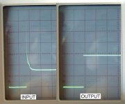
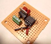
Here's a picture of the "adjuster" and a scope shot at idle that shows the change in pulse length (of fuel injector #1) that's sent to the MPG computer.
 

Attachments
  • mpg readout adjuster.jpg
    mpg readout adjuster.jpg
    46.7 KB · Views: 1,747
Last edited:
Register to hide this ad
Keep in mind... the MPG computer keeps a running average of the your MPG. Its calculation has no concept of "how many miles in this tank."

You (we) are comparing its readout to when we fill up the tank. When you divide your "Miles driven" by your "gallons filled", you're calculating a long term average.

Consider the following series.

1,2,3,3,3,4,3,2,1

The running average (n=1) is: 1.8

The overall average is: 2.44

It'll be interesting to see the results of what kind of adjustment you need. I wouldn't be surprised if a "constant" adjustment was still off...

Nice job, btw.
 
Nice work. I was just wondering what was happening with this project.

Are you going to post the schematic and uCode? I'd be interested in checking it out.
 
CMiYC said:
Keep in mind... the MPG computer keeps a running average of the your MPG. Its calculation has no concept of "how many miles in this tank."

Is this published somewhere?

Since the computer has access to the fuel pulses and speed sensors it would only need to keep a cumulative total of fuel consumption and distance traveled since it was last reset (until the counters overflow) to produce the long term average.

Can you explain how you came up with 1.8? Running averages of size (n) are usually computed by sliding a window of (n) points over your input sequence. For n=1, the running average is the same as the original sequence. Am I confused?
 
CMiYC said:
Keep in mind... the MPG computer keeps a running average of the your MPG. Its calculation has no concept of "how many miles in this tank."

You (we) are comparing its readout to when we fill up the tank. When you divide your "Miles driven" by your "gallons filled", you're calculating a long term average.

Consider the following series.

1,2,3,3,3,4,3,2,1

The running average (n=1) is: 1.8

The overall average is: 2.44

I'd agree that the MPG algorithm has no concept of "what's in the tank", it doesn't need to know that. It's different than the range calculation.

If you reset the MPG computer each time you fill the tank, you can check it's accuracy against miles/gallons because both averages use the same miles traveled and gallons used.

By the way, how did you get 1.8 with n=1 in your example above?
 
rando said:
Nice work. I was just wondering what was happening with this project.

Are you going to post the schematic and uCode? I'd be interested in checking it out.

Thanks, I'll post everything later today when I get home from work. It'll be a little embarrassing though, my "algorithm" is caveman simple.

Later....
 
Iowa4Runner said:
Thanks, I'll post everything later today when I get home from work. It'll be a little embarrassing though, my "algorithm" is caveman simple.

Later....

Cool thanks! Don't worry about the algorithm. Based on the description of what you originally planned to do, I expected it to be simple. I presume you just take readings from a counter in your MCU to determine the pulse length. You then divide the count by 1.12 (or some integer math approximation) and output your fixed pulse while counting down.

Simple things are good. Simple things that work are even better! :D

Also, did you find a source of harness pins? Cut wires? Disassembled the trip computer and did some soldering?
 
Last edited:
By the way, how did you get 1.8 with n=1 in your example above? [/B]


Start with 1 and average that with the second number (2) for a running average of 1.5. Then average that (1.5) with the next number, and so on....
 
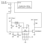
Here's the schematic:

Because the country I live in is overrun with lawyers and adults who never grew up, I should at least attempt to provide a warning about implementing this device. I make no guarantees of any kind regarding this device. Installation of this device requires modification of the vehicle's wiring which may void all warranties and create hazardous situations. Such hazards include, but are not limited to, significant vehicle damage, personal injury, and death.
 

Attachments

  • schematic3.jpg
    schematic3.jpg
    19.2 KB · Views: 1,263
Last edited:
rando said:
I presume you just take readings from a counter in your MCU to determine the pulse length. You then divide the count by 1.12 (or some integer math approximation) and output your fixed pulse while counting down.

Simple things are good. Simple things that work are even better! :D

Also, did you find a source of harness pins? Cut wires? Disassembled the trip computer and did some soldering?

The algorithm increments a 16 bit counter and turns on the output to the MPG computer when the injector is open. Once the injector closes, the counter decrements at an adjustable rate of 8 times the count up rate. Once the counter hits zero it turns off the pulse to the MPG computer. All it does is make the fuel injector pulse to appear ~12% longer than it really is.

As for the wiring... I'm ashamed to say I did cut one wire. The dashed line in the schematic shows the original path of the injector signal before I got my hands on it. I can restore the wiring to near mint condition with minimal effort if needed.
 
LOL, of course you had to stretch the fuel pulse, not shorten it ... my bad.

That's a fairly clever algorithm (IMHO) for adding 12.5%. I also like the way you init'd the hi byte to 1 (instead of 0) so that the countdown detection logic only had to check a single byte. I had to read the code a few times to figure out why you did that.

Nice work.
 
Last edited:
rando said:
LOL, of course you had to stretch the fuel pulse, not shorten it ... my bad.

That's a fairly clever algorithm (IMHO) for adding 12.5%. I also like the way you init'd the hi byte to 1 (instead of 0) so that the countdown detection logic only had to check a single byte. I had to read the code a few times to figure out why you did that.

Nice work.

Thanks. The PIC12 series instruction set is pretty limited and I couldn't come up with a slick way to check the low byte for "underflow" and the high byte for zero at the same time. So like you said, I just preloaded the high byte with 1 so I could ignore the remainder on the low byte once the high byte hit zero.

I'm not sure if you noticed, but the decrement value in the code is 7 instead of 8. This is because there are fewer lines in the decrement loop than the there are in the increment loop, so it runs a little faster in real time.

I'll let you know how the MPG numbers compare after I finish off this tank of gas...
 
Iowa4Runner said:
I'm not sure if you noticed, but the decrement value in the code is 7 instead of 8. This is because there are fewer lines in the decrement loop than the there are in the increment loop, so it runs a little faster in real time.

No, I wasn't familiar with the instruction set so I didn't even look at the constants much -- just your comments. I did count instructions in the loop and was wondering if differences in the two loops had any impact on accuracy. Are all instructions a single cycle? What's the cycle time?
 
rando said:
No, I wasn't familiar with the instruction set so I didn't even look at the constants much -- just your comments. I did count instructions in the loop and was wondering if differences in the two loops had any impact on accuracy. Are all instructions a single cycle? What's the cycle time?

Most instructions take 4 clock cycles, the conditional tests (like btfsc) take 8. It basically boils down to 4 clock cycles per program line. You can use the internal 8 MHz clock or supply an external clock signal up to 40 MHz. If you want to see the datasheet check out-

http://ww1.microchip.com/downloads/en/DeviceDoc/41211B.pdf

Later...
 

Members online

Forum statistics

Threads
278,315
Messages
3,554,102
Members
248,016
Latest member
Advally Service

Trending content

Back
Top