"If I can do It You Can" Behind Grill Light Bar Install

Dang it - I was reading the whole thread last night - I thought i read that you had to jerry rig something to get it all working in the end?!


Not exactly. I did just make sure to add the link to the other thread too. I probably should include what I'm going to write below there too. Or at least have been a bit more descriptive in my other postings.

Basically all I did was take out the two bolts, one of which is visible on the right side of this picture:

http://www.toyota-4runner.org/attac...n-behind-grill-light-bar-install-img_5618.jpg

The other is almost visible on the left side.

On the bracket, I used the top existing holes, and a few metal and rubber washers to mount the bar directly to the angle bracket.

I then used a few rubber washers to raise the base up enough so that the bracket wouldn't tilt forward due to that lip on the motor side of the bumper support.

I then reused the bolt I had taken out to hold bracket in place.

Most of these steps are probably what you'll do with the brackets you bought. And again, those brackets are probably much much nicer than the 4$ ones I used.
 
Last edited:
This is an awesome write-up [MENTION=120701]Cymon[/MENTION]! Exactly what I needed.

I just got the 32" OPT7 and was kind of nervous about wiring it but this is great. I can't wait to install it!

And I really like the concrete angle idea, thanks [MENTION=126085]mcarey86[/MENTION]
 
Question about switch wiring diagram.

In 4Runner dimmer circuit is "high ground" type meaning the positive of the LED light in the switch is connected to +12V and negative of LED light is connected to "high ground" of dimmer. Simply saying the voltage between "high ground" and vehicle ground depends on the dimmer setting - the higher the voltage, the dimmer is light.

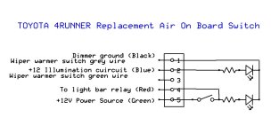
The way all is connected I suspect that the "dimming" circuit expects to work when l illumination is ON. So I don't know if is any problem when we would try to use dimmer when illumination is OFF. Below I attach the schematic of AOB switch.

As you can see it comes only with one "ground" for both LEDs (black wire) which supposed to be connected to dimmer circuit (high ground). I don't see a problem with lighting the "illumination" LED (The light on the switch that comes on when you turn on illumination a car). The problem I see is the light that comes on when switch is in ON position. If green wire is getting +12V from other than illumination circuit the LED drains small current to dimmer circuit. Is it safe for Main Body ECU (the dimmer circuit is in this ECU) ? What happens to this LED when illumination is OFF? Does it react to dimmer setting or light full blast?
 

Attachments

  • Wiring Air On Board switch.JPG
    Wiring Air On Board switch.JPG
    75.3 KB · Views: 1,233
Question about switch wiring diagram.

In 4Runner dimmer circuit is "high ground" type meaning the positive of the LED light in the switch is connected to +12V and negative of LED light is connected to "high ground" of dimmer. Simply saying the voltage between "high ground" and vehicle ground depends on the dimmer setting - the higher the voltage, the dimmer is light.

The way all is connected I suspect that the "dimming" circuit expects to work when l illumination is ON. So I don't know if is any problem when we would try to use dimmer when illumination is OFF. Below I attach the schematic of AOB switch.

As you can see it comes only with one "ground" for both LEDs (black wire) which supposed to be connected to dimmer circuit (high ground). I don't see a problem with lighting the "illumination" LED (The light on the switch that comes on when you turn on illumination a car). The problem I see is the light that comes on when switch is in ON position. If green wire is getting +12V from other than illumination circuit the LED drains small current to dimmer circuit. Is it safe for Main Body ECU (the dimmer circuit is in this ECU) ? What happens to this LED when illumination is OFF? Does it react to dimmer setting or light full blast?

Those are some great questions and honestly above my pay grade. In terms of the main body ECU, the reasoning is discussed extensively in this thread http://www.toyota-4runner.org/5th-gen-t4rs/192198-switch-not-switch.html

For the others [MENTION=83083]rigtec[/MENTION] and [MENTION=81322]barryhiram[/MENTION] are super helpful and could definitely go into the schematics and how it works way better then I could if what you are looking for is not found in the above thread.
 
Last edited:
Question about switch wiring diagram.

In 4Runner dimmer circuit is "high ground" type meaning the positive of the LED light in the switch is connected to +12V and negative of LED light is connected to "high ground" of dimmer. Simply saying the voltage between "high ground" and vehicle ground depends on the dimmer setting - the higher the voltage, the dimmer is light.

The way all is connected I suspect that the "dimming" circuit expects to work when l illumination is ON. So I don't know if is any problem when we would try to use dimmer when illumination is OFF. Below I attach the schematic of AOB switch.

As you can see it comes only with one "ground" for both LEDs (black wire) which supposed to be connected to dimmer circuit (high ground). I don't see a problem with lighting the "illumination" LED (The light on the switch that comes on when you turn on illumination a car). The problem I see is the light that comes on when switch is in ON position. If green wire is getting +12V from other than illumination circuit the LED drains small current to dimmer circuit. Is it safe for Main Body ECU (the dimmer circuit is in this ECU) ? What happens to this LED when illumination is OFF? Does it react to dimmer setting or light full blast?

It reacts to dimmer setting same as illumination. Zero ECU issues here 4 years later. If you're that concerned, you could take the 5th pin (unused) on switch, cut board traces to separate connections on board, cut board shared led ground trace so "switch on" led is separated, connect a dedicated ground wire to 5th pin, then solder lead from pin to ground side of "switch on" led, thus two led's would be separate for both power and ground.
 
It reacts to dimmer setting same as illumination. Zero ECU issues here 4 years later. If you're that concerned, you could take the 5th pin (unused) on switch, cut board traces to separate connections on board, cut board shared led ground trace so "switch on" led is separated, connect a dedicated ground wire to 5th pin, then solder lead from pin to ground side of "switch on" led, thus two led's would be separate for both power and ground.


Thank you! Knew you would come through...lol!
 
It reacts to dimmer setting same as illumination. Zero ECU issues here 4 years later.

Thanks for the input. I guess then the Dimmer circuit in ECU is powered all the time keeping "high ground" voltage regardless if illumination is on or off. Your experience is reassuring. BTW, where did you get the +12V to the switch from? Direct from battery?

you could take the 5th pin (unused) on switch, cut board traces to separate connections on board, cut board shared led ground trace so "switch on" led is separated, connect a dedicated ground wire to 5th pin, then solder lead from pin to ground side of "switch on" led, thus two led's would be separate for both power and ground.

This would be solution if I would want to have one LED run full power regardless of the dimmer setting. But it would be annoying while driving at night.
 
BTW, where did you get the +12V to the switch from? Direct from battery?
.

Yes...A-lot of people tie into the high-beams (see [MENTION=103267]Saker[/MENTION]'s install that I linked in the first post) but I wanted something simple and so that I could turn it on without the ignition "on". I know the risk of leaving on the light but these things are so damn bright I don't know how I could (until I do).

Another route is to add a fuse. See the linked thread in the first post by [MENTION=129593]MTN4RNR[/MENTION] .
 
Last edited:
Hi [MENTION=120701]Cymon[/MENTION]...

This write-up provides such great detail and insight that I wanted to Thank you for all the time and effort you spent to execute it! "...Being such a valuable contribution to these forums, many members (and visitors) will benefit for sure! Five stars***** Keep it up"!

rig
 
Hi [MENTION=120701]Cymon[/MENTION]...

This write-up provides such great detail and insight that I wanted to Thank you for all the time and effort you spent to execute it! "...Being such a valuable contribution to these forums, many members (and visitors) will benefit for sure! Five stars***** Keep it up"!

rig

Thank You!
 
Very very nice write up, man. If it's okay with you I'm going to add it to the Consolidated Lighting Thread!
 
Thanks for this, awesome contribution. I had installed some lights behind the grille of my 2004 Tacoma some 10 years ago with a basic switch and fuse and LOVED having them for driving in remote places. Now that I have the 4runner (which IMO has pretty weak stock lighting) I intend to do the same and have been just avoiding it haha.

Now I am motivated to knock it out once I return from a week up in Montana where I am sure I will be wishing I'd already done it!
 
This would be solution if I would want to have one LED run full power regardless of the dimmer setting. But it would be annoying while driving at night.

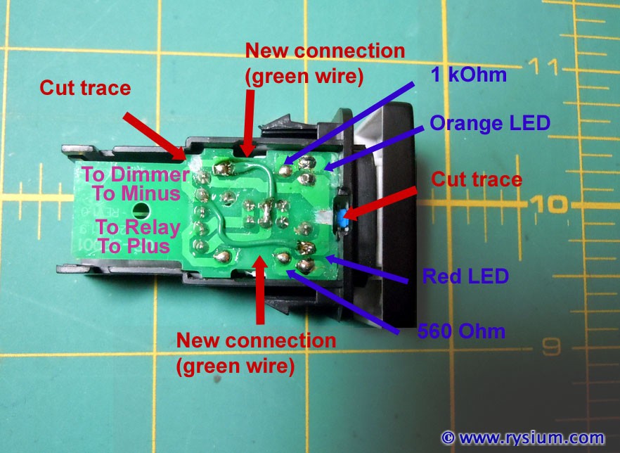
I just remembered that I did similar thing for rear fog lights (EU thing). Besides replacing LED's with correct "orange" color I modified AOB switch as follows:

4runner-fog-light-switch-mod-01.jpg


The top LED, red back-light for the fog light symbol (rear fog light is red) is not dimmable for the purpose of being a "warning light" as it is illegal to run rear fog light when there is no fog (rear fog would blind drivers behind).

For light bar I think I will use illumination +12 to power the switch (light bar via a separate 30A fuse and 40A relay will be powered directly from the battery). This way I will be able to turn on light bar with engine off and no keys in the ignition but the Main Body ECU would still turn it off via timer together with other lights. The additional benefit would be that I will need to run only one wire through the firewall (light bar fuse and relay will be mounted in the engine compartment).

BTW for light bar I did not use original AOB switch but some e-bay knock-out directly from China. From the outside and inside it looks 100% the same for 1/3 of the price. Ah, I'm cheep. I did not want to spend 40 bucks for a switch to 60 dollars light bar - it did not feel right to me. :yo: I replaced both LEDs (bottom is "toyota orange" and top is bright green) and resistors (from 2.2l to 1.5l) anyway so really the only thing left "made in China" is the switch itself, but ... all switches are made in China anyway.:naughty:
 
Confirmation & Questions

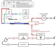
Thanks to everyone for posting all of the LED and switch information in all the threads that are linked through this one. I created the summary diagram below for those
who will be using a OPT7 22inch LED with an AOB switch. It is based on prior instructions and answers to follow-up questions over the past couple days.

Two recommendations when using installing the OPT7 relay harness and an AOB switch.
1) Consider the amperage for the LED bar. For the OPT7 22", the 30A fuse can be replaced with one of lower amperage - I plan on using a 15A fuse in place of the 30A.
2) Wire up the Wiper Warmer wires first and confirm that the AOB switch lights up with the rest of your dash and dims with the T4R dimmer dial. This will also help
prevent accidentally cross-wiring HOT 12V to the ground wire.

(FYI... If anyone has any corrections, please let me know and I'll update.)
 

Attachments

  • LED Wiring JPG.JPG
    LED Wiring JPG.JPG
    108.6 KB · Views: 2,541
Last edited:

Members online

Forum statistics

Threads
278,316
Messages
3,554,120
Members
248,016
Latest member
Advally Service

Trending content

Back
Top