smkd13
New member
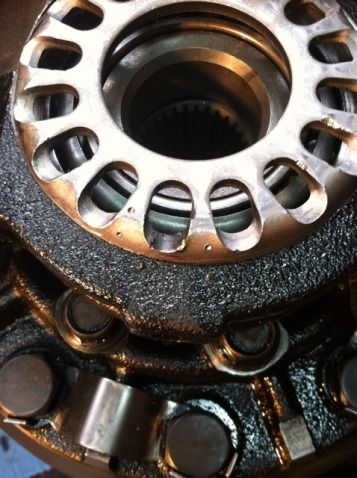
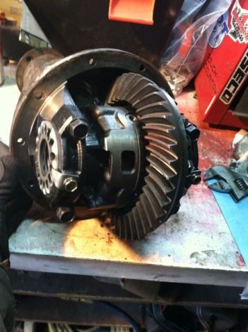
This is a thread dedicated to the installation of a Lock-Right locker.
Thank you [MENTION=88391]NateMob[/MENTION] for your trial and error contribution
Thank you [MENTION=82211]TCMach[/MENTION] for bring up the stud torque issue
Links to install manuals:
Richmond Gear - LockRight Locker Install Manual
US Standard - Spartan Locker Install Manual
This thread can also be used when installing a Spartan locker as well. The design of the two are the same. Please pay attention to the "EDIT" that i have added concerning the thrust washers.
Supplies needed are:
Floor jack, jack stands, and wheel chocks
1/2" socket wrench
3/8” socket wrench
Cresent Wrench
Torque wrench
24mm socket
14mm socket
12mm socket (deep) with extension
10mm hex key or socket
12mm hex key or socket
Oil Drain Pan
Gear Oil
Crush Ring for Drain Plug
Thank you [MENTION=88391]NateMob[/MENTION] for your trial and error contribution
Thank you [MENTION=82211]TCMach[/MENTION] for bring up the stud torque issue
The process is easy but time consuming. But here is my write up on how to install it:
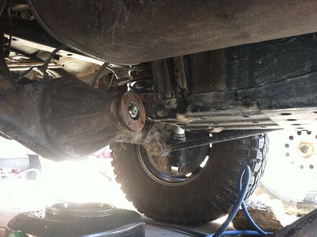
The first step that you have to do is to chalk your wheels and jack up the rear (just enough to get the tires off the ground.) I used jack stand just to hold the axle high enough to get the wheels off the ground.
(Also drain out your fluid at this time as well. (24mm) (36 ft/lbs) When you pull the plug there will be a build up on the end of it. Wipe this onto a clean shop towel and inspect it for any large particles or chunks. A fine powdery dust that is like a thick paste will be present. Normal wear and tear will create this. I reused the crush ring but it was in good shape.)
If you don't chalk then your truck will more than likely start to roll away on you. :loco: but after it is chalked the first thing would be to disconnect the driveline.
These are 14mm bolts and are on there TIGHT!!! but after you get them off just use a hammer and tap the flange a bit and it will loosen up. (Torque spec is 54 ft/lbs)
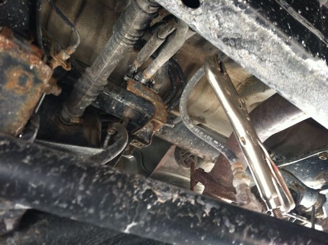
Next if to make life easier when you put it back together use a set of vice-grips to pinch the brake lines (if your sill running OEM).
Remove the tires. (83 ft/lbs)
Next disconnect the e-brake (pinned), brake lines (10mm), and abs sensor (10mm). The ABS sensor is a little hard to get out but just use a flat head screwdriver and ease it out.

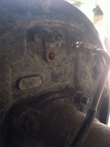
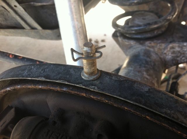
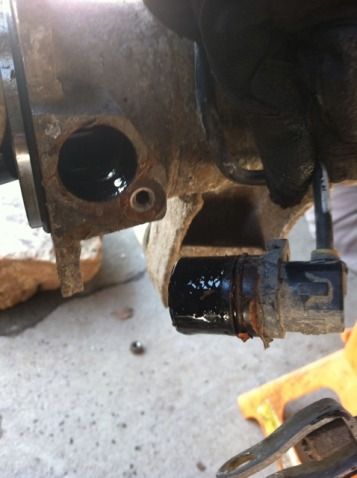
You then separate the axle shafts from the housing. There are 4 nuts (14mm) - (48 ft/lbs) that hold them on. The shafts should separate fairly easy from the housing. I just hit the back of the drum with my palm a few times and they came right out.
I removed the drums when I did this so that I could check the brakes. Good time to check your bearings as well.
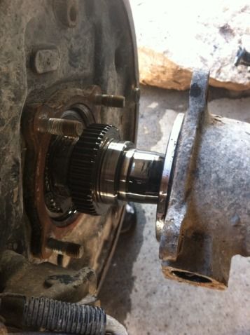
All you really have to do is pull the axle shafts out about 3 - 4 in. but i wanted to bull them all the way out and inspect all the bearings and seals as well. (I don't have any pictures of this but some will get posted later when i do my rear bearings.)
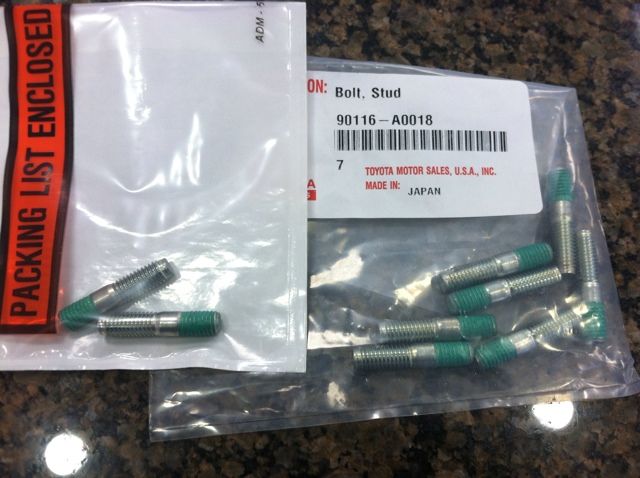
After you pull the shafts out you can then remove the 3rd member. remove all the nuts around the 3rd memeber (12mm). Sometimes the studs will come out when removing the nuts. Good luck finding them. they are a dealer thing. The studs are a M8x1.25 if your wondering and are about $1.74 a piece. They come with a thread locker on them. P/N # 90116-A0018 (NOT A LOT OF DEALERS CARRY THEM SO PROBABLY A GOOD IDEA TO HAVE SOME BEFORE YOU START.)
Using a flat scraper or chisel. lightly separate the 3rd from the housing. Careful cause it is actually kinda heavy and the weight is offset. Once you have it out set it on its side and let the left over gear oil drain out. (use a towel) While it is draining remove the remaining gear fluid from the diff. If you want you can wipe the housing out but not necessary.
Here is some side by side comparisons between the older 3rds and the new 3rds. The first one is out of an 81 IIRC and the second one is out of mine. Notice the difference in the carriers. You will see the bigger difference later on.
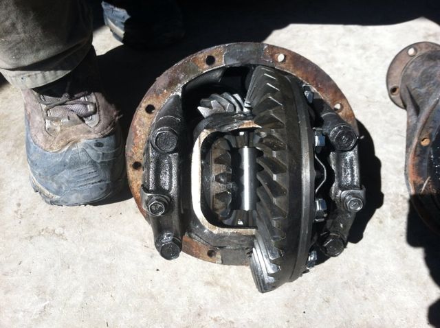
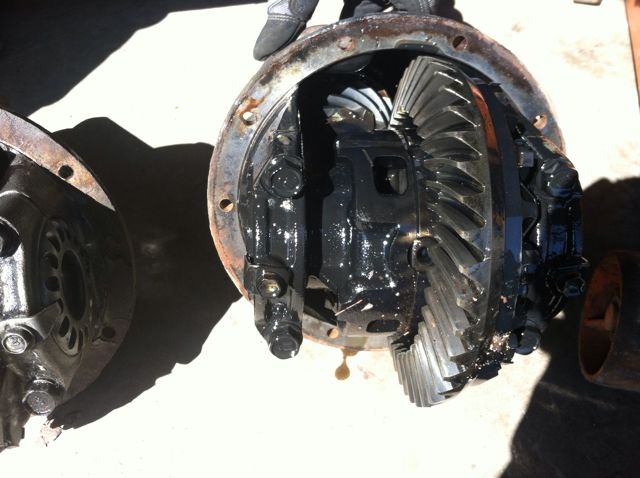
Next I cleaned off all the remaining fluid and metal dust. (normal wear). I used brake cleaner to do this. Worked great. Now we can get onto the fun stuff
Mark each adjuster ring on each side so that you know where they are suppose to be at and as well what side they go on. I used a center punch for this but you can use a sharpie or paint pen or whatever. JUST MARK THEM!!!
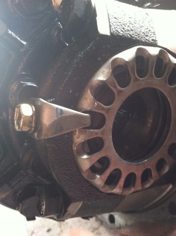
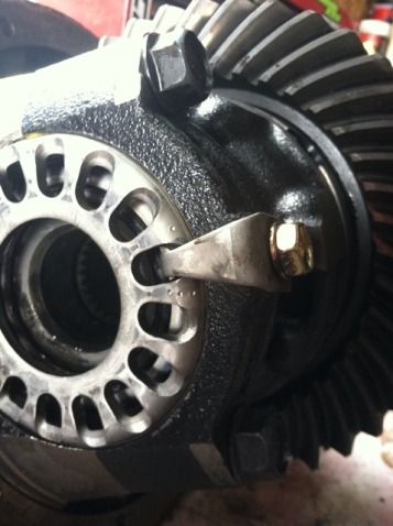
next remove the clips that hold the adjuster nut in place (12mm)

Then remove the two bolts on the top cover for the carrier bearings (17mm)
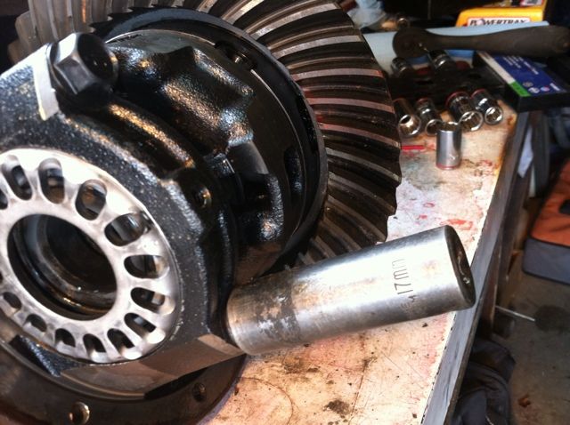
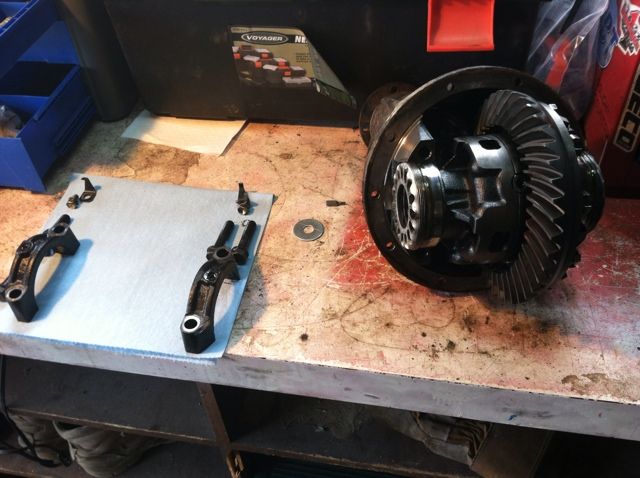
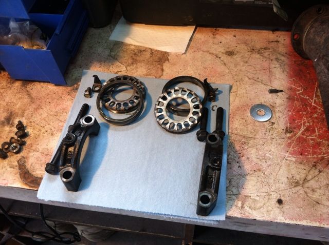
I used a shop towel to keep things organized:
To remove the carrier you have to loosen the adjuster rings, this can be done with a screwdriver, punch, or just a 3/8 extension.
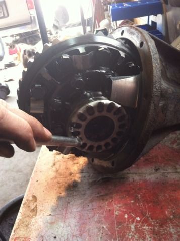
it will take about one full turn to get them loose enough to be able to remove them. just lightly tap and it will turn. Place the adjuster rings and the outer races to the side Again keep the sides separated
Thank you [MENTION=88391]NateMob[/MENTION] for your trial and error contribution
Thank you [MENTION=82211]TCMach[/MENTION] for bring up the stud torque issue
Links to install manuals:
Richmond Gear - LockRight Locker Install Manual
US Standard - Spartan Locker Install Manual
This thread can also be used when installing a Spartan locker as well. The design of the two are the same. Please pay attention to the "EDIT" that i have added concerning the thrust washers.
Supplies needed are:
Floor jack, jack stands, and wheel chocks
1/2" socket wrench
3/8” socket wrench
Cresent Wrench
Torque wrench
24mm socket
14mm socket
12mm socket (deep) with extension
10mm hex key or socket
12mm hex key or socket
Oil Drain Pan
Gear Oil
Crush Ring for Drain Plug
Thank you [MENTION=88391]NateMob[/MENTION] for your trial and error contribution
Thank you [MENTION=82211]TCMach[/MENTION] for bring up the stud torque issue
The process is easy but time consuming. But here is my write up on how to install it:
The first step that you have to do is to chalk your wheels and jack up the rear (just enough to get the tires off the ground.) I used jack stand just to hold the axle high enough to get the wheels off the ground.
(Also drain out your fluid at this time as well. (24mm) (36 ft/lbs) When you pull the plug there will be a build up on the end of it. Wipe this onto a clean shop towel and inspect it for any large particles or chunks. A fine powdery dust that is like a thick paste will be present. Normal wear and tear will create this. I reused the crush ring but it was in good shape.)
If you don't chalk then your truck will more than likely start to roll away on you. :loco: but after it is chalked the first thing would be to disconnect the driveline.
These are 14mm bolts and are on there TIGHT!!! but after you get them off just use a hammer and tap the flange a bit and it will loosen up. (Torque spec is 54 ft/lbs)
Next if to make life easier when you put it back together use a set of vice-grips to pinch the brake lines (if your sill running OEM).
Remove the tires. (83 ft/lbs)
Next disconnect the e-brake (pinned), brake lines (10mm), and abs sensor (10mm). The ABS sensor is a little hard to get out but just use a flat head screwdriver and ease it out.
You then separate the axle shafts from the housing. There are 4 nuts (14mm) - (48 ft/lbs) that hold them on. The shafts should separate fairly easy from the housing. I just hit the back of the drum with my palm a few times and they came right out.
I removed the drums when I did this so that I could check the brakes. Good time to check your bearings as well.
All you really have to do is pull the axle shafts out about 3 - 4 in. but i wanted to bull them all the way out and inspect all the bearings and seals as well. (I don't have any pictures of this but some will get posted later when i do my rear bearings.)
After you pull the shafts out you can then remove the 3rd member. remove all the nuts around the 3rd memeber (12mm). Sometimes the studs will come out when removing the nuts. Good luck finding them. they are a dealer thing. The studs are a M8x1.25 if your wondering and are about $1.74 a piece. They come with a thread locker on them. P/N # 90116-A0018 (NOT A LOT OF DEALERS CARRY THEM SO PROBABLY A GOOD IDEA TO HAVE SOME BEFORE YOU START.)
Using a flat scraper or chisel. lightly separate the 3rd from the housing. Careful cause it is actually kinda heavy and the weight is offset. Once you have it out set it on its side and let the left over gear oil drain out. (use a towel) While it is draining remove the remaining gear fluid from the diff. If you want you can wipe the housing out but not necessary.
Here is some side by side comparisons between the older 3rds and the new 3rds. The first one is out of an 81 IIRC and the second one is out of mine. Notice the difference in the carriers. You will see the bigger difference later on.
Next I cleaned off all the remaining fluid and metal dust. (normal wear). I used brake cleaner to do this. Worked great. Now we can get onto the fun stuff
Mark each adjuster ring on each side so that you know where they are suppose to be at and as well what side they go on. I used a center punch for this but you can use a sharpie or paint pen or whatever. JUST MARK THEM!!!
next remove the clips that hold the adjuster nut in place (12mm)
Then remove the two bolts on the top cover for the carrier bearings (17mm)
I used a shop towel to keep things organized:
To remove the carrier you have to loosen the adjuster rings, this can be done with a screwdriver, punch, or just a 3/8 extension.
it will take about one full turn to get them loose enough to be able to remove them. just lightly tap and it will turn. Place the adjuster rings and the outer races to the side Again keep the sides separated
Last edited:
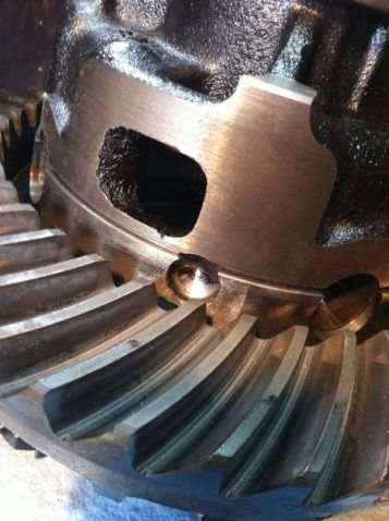
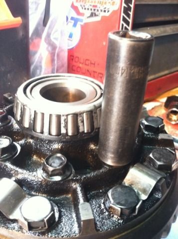
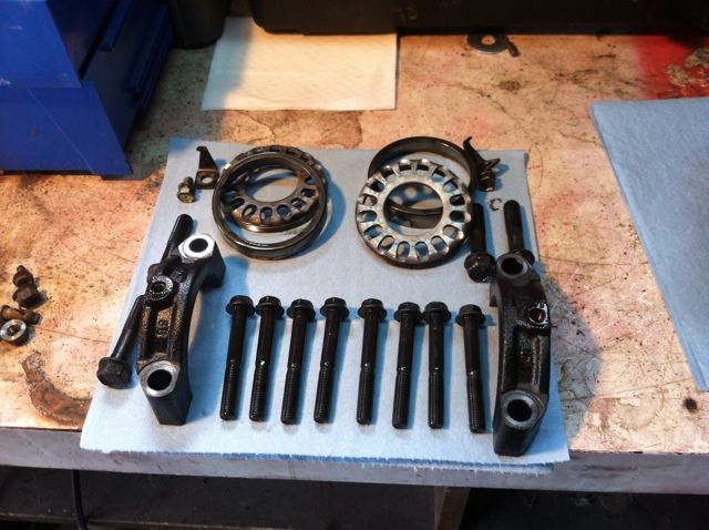
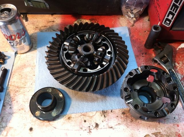
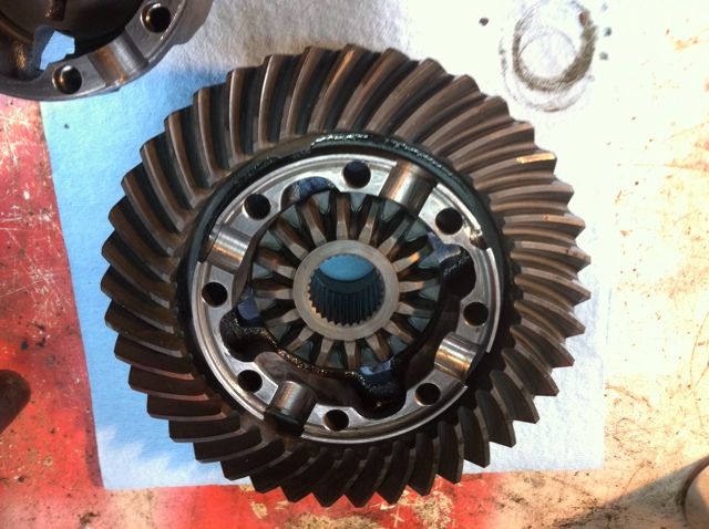
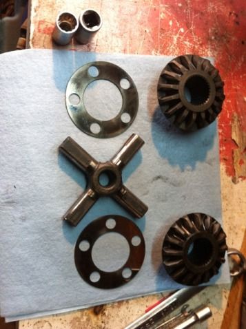
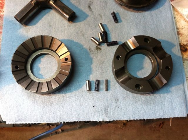
 This is everything that comes in the Lock-Right box: