Mirror Brackets: CAD Design and CNC Work?

Yeah put it on a dark back ground. Be easier to see the edges that way.

I guess I could load straight into rhino and trace it but I find it easier to resize it in illustrater and swap over the vector drawing.
 
Troubleshooting

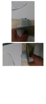
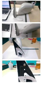
So I attached some photos of the template on the mirror, and I know this template is not FINAL, but it gives you a rough idea of how it mounts to the mirror and where modifications will need to be made. ANY input you have would be greatly appreciated.

If you look where the bracket attaches to the mirror, the solid metal housing where the bolts attach has a larger ring beneath it that may cause problems with the original design.
 

Attachments

  • Template 1.jpg
    Template 1.jpg
    133.4 KB · Views: 267
Troubleshooting

So here is a better picture of what I'm talking about. It looks like there is a gradual slope to the mirror plate, which I've marked with a red line in the picture. From that view, you can see where the second ring may cause some interference.
 

Attachments

  • Template 2.jpg
    Template 2.jpg
    92.8 KB · Views: 257
How much room is there between the bottom of the mirror and the bracket? If I were to use that back hole to mount some lights underneath the bracket is there enough clearance for that? Also with the slope of the mirror plate could this area be used to run the wires from whatever we decide to mount on these? Maybe use a softer rubber seal that will still create a waterproof seal but allow for wires to be run? Just a thought, I know nothing about this stuff.

Sent from my SM-N910V using Tapatalk
 
Last edited:
How much room is there between the bottom of the mirror and the bracket? If I were to use that back hole to mount some lights underneath the bracket is there enough clearance for that? Also with the slope of the mirror plate could this area be used to run the wires from whatever we decide to mount on these? Maybe use a softer rubber seal that will still create a waterproof seal but allow for wires to be run? Just a thought, I know nothing about this stuff.

Sent from my SM-N910V using Tapatalk

There is 7/8"- 1" of clearance between the bottom of the mirror and the top of the bracket, depending on where you mount it. The closer to the mirror mounting plate, the less room there is due to the sloping shape of the mirror bracket.

I suppose that the easiest route for the wires is directly under the plate. This may require some modification or crowding of the seal at the bottom of the mirror. You could use some silicon to seal around it.
 
There is 7/8"- 1" of clearance between the bottom of the mirror and the top of the bracket, depending on where you mount it. The closer to the mirror mounting plate, the less room there is due to the sloping shape of the mirror bracket.

I suppose that the easiest route for the wires is directly under the plate. This may require some modification or crowding of the seal at the bottom of the mirror. You could use some silicon to seal around it.
Exactly what I was thinking. Done right, this would probably be the cleanest route. I know the other mounts you referenced had cb antennaes mounted to these and that would be a very large wire to try and shove through there. Because of its proximity to the corner of the hood that would probably be the next best spot. I'm excited to see the end result. Please pm me when these are made and I would be happy to get a pair from you.

Sent from my SM-N910V using Tapatalk
 
Yeah put it on a dark back ground. Be easier to see the edges that way.

I guess I could load straight into rhino and trace it but I find it easier to resize it in illustrater and swap over the vector drawing.

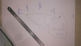
I hope this helps. This is the retooled version that lays as flat as possible against the mirror. If I can just get one made, I can make corrections to the design as needed.

I know this will require some squaring of the bracket slots on the bottom plate.

Let me know what else you need!
 

Attachments

  • Template 2 T4R.jpg
    Template 2 T4R.jpg
    39.3 KB · Views: 241
Has anyone had success in turning the drawing into a CAD design yet? I'm thinking this may be a tougher route to go, but I may have another option/idea if this isn't working for others.

I noticed that at the bottom of the mirror there are three screws that hold the mirror to the bracket. How hard would it be to create a bracket that would fit in the holes and sit directly beneath the mirror while using slightly longer bolts/screws to hold the mirror in place?

I'm really open to any thoughts or ideas here.
 
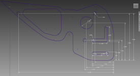
[MENTION=96630]jhuerta22[/MENTION] Do you have an email? Here's what you want. I though about making some of these a while ago, but didn't have a press brake. I made one for our shop press last weekend and seeing as you've done the leg work I will do you a favor and make your drawing into a dxf and pdf. Please print it out and compare it and make sure it works. Also I have dimensioned all the holes, if the dimensions are wrong change the numbers so it will be easy for me to just plug them in. I referenced everything to the bottom right hand corner, you can make these measurements using a ruler square or a caliper fairly accurately.

This is one someone makes for a Landcruiser 80 series.
Ditch Light Mirror Mounts - FJ80 Toyota Land Cruiser Lexus LX450
 

Attachments

  • Mirror ditch bracket.png
    Mirror ditch bracket.png
    51.9 KB · Views: 228
Last edited:
[MENTION=100116]D Farms[/MENTION] I just pm'd you. Much appreciated! The only thing I can think of on the design is the large hole in the bottom plate should be right at 1.25", but I'm sure I can make the corrections on that! Still, much appreciated!
 
I'm starting to work an a secondary design that would attach to the mirror bracket itself using the existing three screw holes on the bottom of the mirror. The bracket itself is pretty substantial and I think it would be an easier mounting point than mount that would sandwich between the mirror and the door frame.

Any thoughts? :shrug:
 
Sounds good to me. How thick will the metal be?


Sent from my SM-N910V using Tapatalk


The plate will most likely be 1/8" thick if I go the route of the bracket between the mirror and the door. Otherwise, I might bump it up to 3/16" If I find a way to mount it directly under the mirror.
 
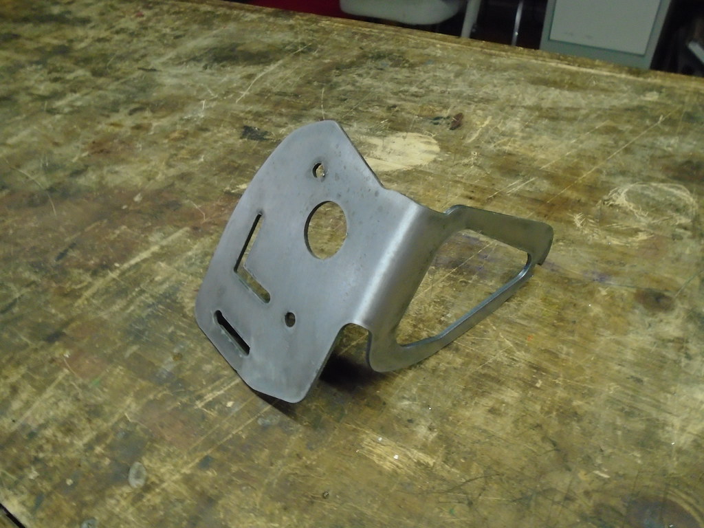
I made a test one last night, Im definitely going to redesign the mounting surface, its just a copy of the "yodateq" mounting plate and has way too many holes.

26672034976_79e9639c7e_b.jpg


thumbnail.asp
 
Last edited:
I made a test one last night, Im definitely going to redesign the mounting surface, its just a copy of the "yodateq" mounting plate and has way too many holes.

26672034976_79e9639c7e_b.jpg


thumbnail.asp

That looks amazing! Nice work on the bracket! The general idea behind the mounting plate was to mimic the yodateq design to give people opportunities to add different light setups and broaden the marketability of the bracket. Honestly if I were to have my own set I think I'd simplify it down to just holding the lights.
 
If end up selling some, of a slightly different design, they will be the same price as the yodateq ones, which is $129 including shipping.
 

Members online

Forum statistics

Threads
278,310
Messages
3,554,079
Members
248,016
Latest member
Advally Service

Trending content

Back
Top