Here’s how I added power outlets and USB ports to my 4th-gen 4Runner. Unlike most of the mods, I found here, I wanted a combination of switched and constant-power outlets.
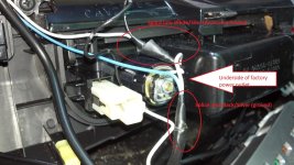
Specifically, I wanted to have the factory power outlet continue to be controlled by the ignition key (“accessory power”)… for my GPS. I only need that powered up when I’m driving.
The new power outlets are for charging my cellphones and Bluetooth devices. I want them to charge when the car is running (accessory power), but also have the ability to charge them when the car is off (“constant power”).
Rather than having these new outlets draw power all the time, I have the constant-power controlled by a rocker switch in the center console.
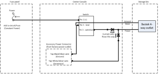
To summarize: the new outlets get power when the car is running, OR when the rocker switch is On; otherwise they don’t get power. The factory power outlet remains unchanged.
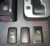
This mod uses parts and info from several other threads, plus a few extra diodes, to complete the build.
Step 1: Remove the center console cover that goes around the shifter.
It’s surprisingly easy. Instructions are at:How to Remove the Navigation Head Unit from a 2003 Toyota 4Runner
Step 2: Get constant-power over to the center console.
I purchased a device that many call an “Add a Circuit,” from Autozone ($12). Mine was listed as a “Cooper Bussmann/ATM fuse tap” Cooper Bussmann/ATM fuse tap (BP-HHH-RP) | Fuse and Accessories | AutoZone.com This is what it looks like:

To decide where to put it in the fusebox, I used a voltmeter to find an empty fuse location that had constant power. In my case (2007, SR5, no Aux power, no seat heaters), it was in the location shown:
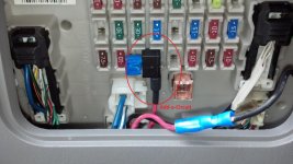
The only tricky/confusing part is that I didn’t get power when I first inserted the Add-a-circuit. After some head-scratching, I realized that the device is directional… I had to remove the Add-a-circuit, and insert it pointing the other direction.
I connected a wire to the end of the Add-a-circuit and snaked it over to the center console opening.
Note: For the duration of this build, keep the Add-a-circuit unplugged from the fuse box. Remember, this is constant-power and you’ll find that you will cause a short with your screwdriver and have to replace the fuse if you don’t.
Step 3: Insert switch.
I purchased a lighted toggle switch from oznium for $12 (Scion OEM Style Lighted Rocker Switch). I got the amber, so it would match the lights on the dash.

I popped out one of the blank covers, and inserted the switch. It didn’t quite fit (the switch is a little big), but about 30 seconds with a file made the inside of the opening a bit bigger, and the switch now fits snugly in place.
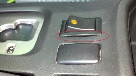
Note: From above, the switch looks good. From the side, you can see a slight gap between the switch trimplate and the center console cover. Given the low price, I don’t mind.
Step 4: Insert the new power outlets in the center console bin
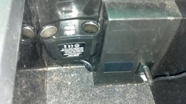
I purchased a Bestek “Four way socket adapter” (two-outlet and 2-USB) from AmazonAmazon.com: BESTEK car cigarette lighter socket usb car charger Cigarette Lighter adapter dc to dc charger usb car adapter socket car splitter adapter 4 way plug socket usb outlet four way car splitter charger: Camera & Photo for about $12.
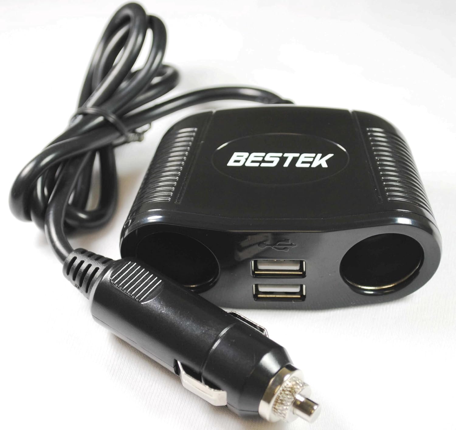
I snipped the cigarette-lighter adapter off the end, so I just had to thread the wire from the storage bin into the center console opening.
Using a drill and a bit just larger than the cable (about ¼”), I drilled a hole from the bin into the center console opening, and threaded the wire through it.
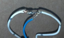
To prepare for wiring, I bared the wires (inner is positive, outer braid is the ground).
(cont)
Specifically, I wanted to have the factory power outlet continue to be controlled by the ignition key (“accessory power”)… for my GPS. I only need that powered up when I’m driving.
The new power outlets are for charging my cellphones and Bluetooth devices. I want them to charge when the car is running (accessory power), but also have the ability to charge them when the car is off (“constant power”).
Rather than having these new outlets draw power all the time, I have the constant-power controlled by a rocker switch in the center console.
To summarize: the new outlets get power when the car is running, OR when the rocker switch is On; otherwise they don’t get power. The factory power outlet remains unchanged.
This mod uses parts and info from several other threads, plus a few extra diodes, to complete the build.
Step 1: Remove the center console cover that goes around the shifter.
It’s surprisingly easy. Instructions are at:How to Remove the Navigation Head Unit from a 2003 Toyota 4Runner
Step 2: Get constant-power over to the center console.
I purchased a device that many call an “Add a Circuit,” from Autozone ($12). Mine was listed as a “Cooper Bussmann/ATM fuse tap” Cooper Bussmann/ATM fuse tap (BP-HHH-RP) | Fuse and Accessories | AutoZone.com This is what it looks like:
To decide where to put it in the fusebox, I used a voltmeter to find an empty fuse location that had constant power. In my case (2007, SR5, no Aux power, no seat heaters), it was in the location shown:
The only tricky/confusing part is that I didn’t get power when I first inserted the Add-a-circuit. After some head-scratching, I realized that the device is directional… I had to remove the Add-a-circuit, and insert it pointing the other direction.
I connected a wire to the end of the Add-a-circuit and snaked it over to the center console opening.
Note: For the duration of this build, keep the Add-a-circuit unplugged from the fuse box. Remember, this is constant-power and you’ll find that you will cause a short with your screwdriver and have to replace the fuse if you don’t.
Step 3: Insert switch.
I purchased a lighted toggle switch from oznium for $12 (Scion OEM Style Lighted Rocker Switch). I got the amber, so it would match the lights on the dash.
I popped out one of the blank covers, and inserted the switch. It didn’t quite fit (the switch is a little big), but about 30 seconds with a file made the inside of the opening a bit bigger, and the switch now fits snugly in place.
Note: From above, the switch looks good. From the side, you can see a slight gap between the switch trimplate and the center console cover. Given the low price, I don’t mind.
Step 4: Insert the new power outlets in the center console bin
I purchased a Bestek “Four way socket adapter” (two-outlet and 2-USB) from AmazonAmazon.com: BESTEK car cigarette lighter socket usb car charger Cigarette Lighter adapter dc to dc charger usb car adapter socket car splitter adapter 4 way plug socket usb outlet four way car splitter charger: Camera & Photo for about $12.
I snipped the cigarette-lighter adapter off the end, so I just had to thread the wire from the storage bin into the center console opening.
Using a drill and a bit just larger than the cable (about ¼”), I drilled a hole from the bin into the center console opening, and threaded the wire through it.
To prepare for wiring, I bared the wires (inner is positive, outer braid is the ground).
(cont)