My LED Bumper Light conversion

cdoyle

Member
After reading all the pages of the Bumper Light Conversion that others had done. I wanted to do this mod too, but I wanted something a little different.

I wanted the look of the light to be similar to the LED tail lights I did last summer (see link in sig for pictures of those).

Anywho, thanks to Pennywise for being the first to see if the lens and the housing could come apart! That made this mod for me much easier :)


The first thing I did was removed the lens from the housing, by baking them in the oven at 300 for about 8 minutes. Then carefully pulled the lens away from teh housing (also being careful not to brake the tabs.)

lensremoved.jpg


Now that I had access to the inside part of the housing, I cut my PCB to match.

pcbcuttoshape.jpg


Now that I have my template, I started placing my superflux LED's (HPWT-MD00-F4000) on to the PCB. I decided to keep it simple, and just have 5 rows of LEDs with 5 LEDs per row.

completedpcb.jpg


After soldering all those LEDs onto the board, I was ready to place it into the housing. I used epoxy to secure it, to the housing. I ran the wires out the vent hole in the back.
pcbinstalled.jpg


Once the epoxy was dry, I took some adhesive and put the lens back onto the housing.

Ready for a test run

testrun.jpg


Almost done!
I wasn't able to get both installed tonight, but here is a teaser of just one side. (pics dont' do these justice at all.)

Just tail lights
tailandbumperparking.jpg


and here is what it looks like when the brakes are applied.

tailandbumpebrake.jpg


It looks great in person. Looks just like an OEM type light.

I'll try and get better pics tomorrow, and with both sides installed.
 
Register to hide this ad
Nice job, I'm sure they will look excellent when both are in.

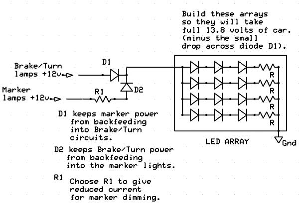
One question. How did you wire the LED's for dual brightness (tail light & brake light)? Is it as simple as applying different operating voltages to them? i.e. lower voltage for dimmer light output and higher voltage for brighter output?
 
OK, don't have much time tonight but I was able to get the other one in, and took some pics.

brakeandbumper3a.jpg


brakeandbumper4.jpg
brakeandbumper6.jpg

brakeandbumper7.jpg
tailandbumper2.jpg
 
Last edited:
OUTRNNR said:
Nice job, I'm sure they will look excellent when both are in.

One question. How did you wire the LED's for dual brightness (tail light & brake light)? Is it as simple as applying different operating voltages to them? i.e. lower voltage for dimmer light output and higher voltage for brighter output?


Here is the schematic I based my design from.

simpleLEDarraypowering.jpg


Azdave over at HIDPlanet helped me with this. There a bunch of great guys over there that will help you with LED retros.
 
do you have pics of the back of the pcb board? you you know what diodes you used? are you assuming a 0.7 V drop across the diode? do you know what the resistor values are? if not, color scheme will do fine if you know those?

hard to tell from the pics, but brown-black-purple? and brown-brown-brown for the other one?
 
In my rush to get these put back together, I forgot to take a pic of the back of the circuit board. Sorry :(

The resistors I used were for R1 was 2.2k ohm. I first used a potentiometer and adjusted it until I got the brightness I wanted. I then took my multimeter and read what resistance it was.

For R2 I used 47ohm, the design actually called for a 39 ohm but radio shack were out of those. But even with the 47 ohm, they are still pretty bright.

These LEDs have a max rating of 70ma, to be safe, I went under that and used around 60ma.

Here is a nice little calculator to help you figure out your design

http://led.linear1.org/led.wiz
 
cdoyle said:
In my rush to get these put back together, I forgot to take a pic of the back of the circuit board. Sorry :(

The resistors I used were for R1 was 2.2k ohm. I first used a potentiometer and adjusted it until I got the brightness I wanted. I then took my multimeter and read what resistance it was.

For R2 I used 47ohm, the design actually called for a 39 ohm but radio shack were out of those. But even with the 47 ohm, they are still pretty bright.

These LEDs have a max rating of 70ma, to be safe, I went under that and used around 60ma.

Here is a nice little calculator to help you figure out your design

http://led.linear1.org/led.wiz
cool.. thanks for the info..
 
Derek said:
Whoa, very cool. If I knew how to do circuit boards like that, I'd do this same thing. :cool:

yeah very kewl work. Not sure if you would make some "kits" in case a member would like to have this on their truck but not exactly mechanically inclined. Just a thought
 
sharp4runr said:
yeah very kewl work. Not sure if you would make some "kits" in case a member would like to have this on their truck but not exactly mechanically inclined. Just a thought


hmmm I'll keep that in mind :)

but really it isn't very hard too do. Little time consuming soldering the LEDs in place but other then that, not too bad.
 
YSutarko said:
so, does NE1 able to open the taillight?

The tail lights use a different glue, that doesn't loosen up when heated. I tried :(

The only way to get in there is to cut the back apart, which is what I did. And actually it wasn't that bad. I cut just enough to fit the module in there, then just glued it all back together.

check out the link in my sig for the tail lights.
 
cdoyle said:
hmmm I'll keep that in mind :)

but really it isn't very hard too do. Little time consuming soldering the LEDs in place but other then that, not too bad.

You really should considering making kits. I'd definitely pick one up. That's a sweet mod!!! Nice job.
 
Cool mod. I new you'll come up with the idea like this just take you some time. But the project you've done is great.
 
AlexJet said:
Cool mod. I new you'll come up with the idea like this just take you some time. But the project you've done is great.

Thanks, I'm really happy with how they turned out. I have been wanting to do this forever, just never had the time to start. Finally took some time off, and that was the first thing I did :)
 
cdoyle said:
The tail lights use a different glue, that doesn't loosen up when heated. I tried :(

cdoyle,

I will agree (last post on page 1)


Nice job. I couldn't have done it better myself. Thanks for the circuit diagram as well. I have spent a good deal of time trying to figure out how to get the dim/bright effect and thought that it had to do with cleverly place diodes, but never really attempted any of my ideas. When I planned on doing the tails, I was just going to use 15 leds for for parking and 35 or so wired for brake, so there would be 2 independent circuits. I didn't really like this method, and figured there was a way to control current with the 2 inputs (tail and brake).

Although, the door, running board and licence plate lights were done in this manner, I just don't feel like baking my bumper lights again. I am impressed with the light tower 2 bulb. The only thing that I needed to do was to add a diode on the tail circuit. What happened was that brake was back feeding into the tail circuit and the light would simply not illuminate. I believe it worked fine as tail only and as brake only, but nothing when both were active. I didn't think that you needed to do that with the pre-made bulbs, but it works now and I'm happy.

Good job again. It's always nice to see others that have just as much time on their hands as I do.

Cdoyle, any thoughts on using 12V voltage regulators? I heard that these would be good to prevent overdriving the leds. I picked up a few and did some measurements, but I figured that just assuming 13.5 or 14 should be sufficient. I'm just curious if you have thought of using them.

Tom
 
YSutarko said:
so, does NE1 able to open the taillight?
YSutarko,

Nope the OEM tails are not able to be opened using the oven method. You may be able to bake aftermarket ones, provided they use a different adhesive.

Tom
 
Pennywise said:
cdoyle,

I will agree (last post on page 1)


Nice job. I couldn't have done it better myself. Thanks for the circuit diagram as well. I have spent a good deal of time trying to figure out how to get the dim/bright effect and thought that it had to do with cleverly place diodes, but never really attempted any of my ideas. When I planned on doing the tails, I was just going to use 15 leds for for parking and 35 or so wired for brake, so there would be 2 independent circuits. I didn't really like this method, and figured there was a way to control current with the 2 inputs (tail and brake).

Although, the door, running board and licence plate lights were done in this manner, I just don't feel like baking my bumper lights again. I am impressed with the light tower 2 bulb. The only thing that I needed to do was to add a diode on the tail circuit. What happened was that brake was back feeding into the tail circuit and the light would simply not illuminate. I believe it worked fine as tail only and as brake only, but nothing when both were active. I didn't think that you needed to do that with the pre-made bulbs, but it works now and I'm happy.

Good job again. It's always nice to see others that have just as much time on their hands as I do.

Cdoyle, any thoughts on using 12V voltage regulators? I heard that these would be good to prevent overdriving the leds. I picked up a few and did some measurements, but I figured that just assuming 13.5 or 14 should be sufficient. I'm just curious if you have thought of using them.

Tom

Thanks!

Over at HIDPlanet, the guys who really get into these Retros all use Voltage regulators and also Pulse Width Modulators for their circuits.

A Regulator would be ideal for these circuits, but before I started this I knew that space was going to be an issue. There isn't much room inside these lens. So I decided to just use resistors, my Peterson Modules use just resistors and diodes, and they have seemed to hold up so far.
 
Pennywise said:
cdoyle,

I will agree (last post on page 1)


Nice job. I couldn't have done it better myself. Thanks for the circuit diagram as well. I have spent a good deal of time trying to figure out how to get the dim/bright effect and thought that it had to do with cleverly place diodes, but never really attempted any of my ideas. When I planned on doing the tails, I was just going to use 15 leds for for parking and 35 or so wired for brake, so there would be 2 independent circuits. I didn't really like this method, and figured there was a way to control current with the 2 inputs (tail and brake).

Although, the door, running board and licence plate lights were done in this manner, I just don't feel like baking my bumper lights again. I am impressed with the light tower 2 bulb. The only thing that I needed to do was to add a diode on the tail circuit. What happened was that brake was back feeding into the tail circuit and the light would simply not illuminate. I believe it worked fine as tail only and as brake only, but nothing when both were active. I didn't think that you needed to do that with the pre-made bulbs, but it works now and I'm happy.

Good job again. It's always nice to see others that have just as much time on their hands as I do.

Cdoyle, any thoughts on using 12V voltage regulators? I heard that these would be good to prevent overdriving the leds. I picked up a few and did some measurements, but I figured that just assuming 13.5 or 14 should be sufficient. I'm just curious if you have thought of using them.

Tom

Just wondering, did you say the running boards can be opened up, by baking them?

Chris
 

Members online

Forum statistics

Threads
278,308
Messages
3,554,057
Members
248,016
Latest member
Advally Service

Trending content

Back
Top