Hi Moto69Joe,
I'm no guru but I think I see what you're wanting to do. Yes it can be done using two
SPDT relays or one
DPDT relay! The relays need to be located at the
Driverside 'C' Pillar which is where the exterior lighting power junction buss is located. I would advise you to use one
AOB Toyota Factory style dash switch for simplicity... Please excuse my chicken scratching diagram, it's really simple if you take your time and follow it!
On the relays you'll chose to use the
#30 to #87A (Normally closed contact) terminals to break the lighting circuit at the junction. So your switch will remain turned off for normal on-road driving. When hunting you'll opt to turn the switch on; that will break the circuit to the...
Stop lights, tail lights, back-up lights, marker lights...etc. I didn't mark the spot where you would need to add an additional relay to disable the headlights; figure you could just turn them off if needed... "See the three page wiring scheme below":
 ABOVE:
 #5 wire w/BLUE trace shows the hot wire which feeds the tail relay from the main 140A ALT Fuse. From there (
10A Tail Fuse) you see the #4 wire w/PINK trace going to the Rear Lighting junction located in the lower
'C' Pillar BELOW: This #4 wire is where you'll need to add a set of N/C relay contacts so that when you push the dash switch, these contacts will open; killing power to one portion of that junction.
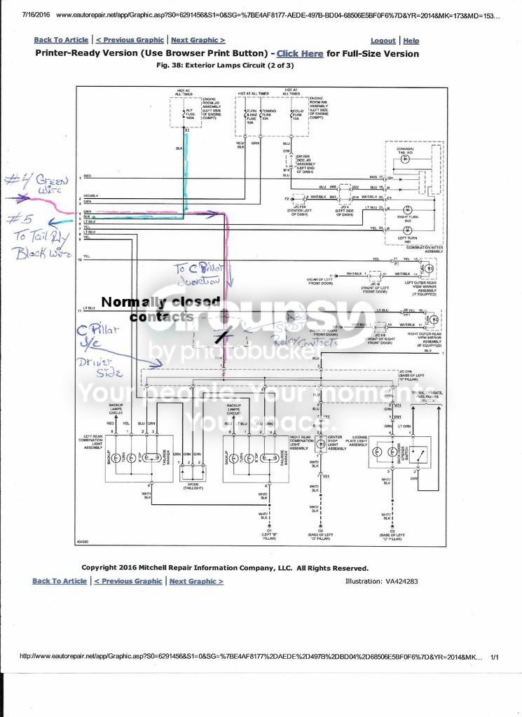 BELOW
BELOW You'll also need to add a second set of
N/C (normally closed contacts) (see yellow trace and N/C relay that's sketched in) so you can kill the remaining portion of the power to that junction from the brake lights. Now the entire
'C' Pillar junction is dead as long as the AOB dash switch is on! You can energize both of these relays simultaneously using only one dash switch. Just find an available power source; preferably one that goes off when the ignition switch is turned off to prevent an accidental over night on mode... I like to use the center console power point socket below the headunit.
To do this, just run the Lt Green
HOT wire from the power point socket to the Green/Yel AOB switch power-in (Common) terminal. Now run the RED/Green wire from the AOB switch to the
#85 Term (Coil) on the relay. Locate the
#86 Term and connect it to a suitable earth ground; now your trigger circuit is complete! You don't need to run two hot wires to those relays, just pull one Hot wire to one relay from the dash and use a pigtail jumper from one relay to the other relay #85 Terminal and again, ground terminal #86.
The remaining
BLUE/Yel wire on the AOB switch is for illuminating the etched switch face icon to glow when you're using the parking lights (Optional). You can connect that wire to a neighboring switch on the dash (Green wire) that illuminates with the parking lights on, and connect the switch's BLACK wire to the (Gray wire) on the neighboring switch as well so the AOB switch will behave exactly as the factory switches do!
 PS:
PS: you should be able to use the dimmer dial to dim the dash lighting when in stealth mode! I hope you will find this 'sketched up' diagram somewhat helpful and let us know how you're making out with this project,
'Best to you'! rig



