On-Demand Rear Seat Footwell Lights

ElectroBoy

Banned
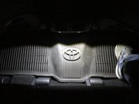
Ever have a backseat passenger drop something on the floor at night and they want to turn on the overhead light to find it? Instead of distracting or blinding you while you drive, have them turn on the rear footwell lights. But wait, most 5th Gens don’t have them, at least my 2018 ORP doesn’t.

After installing my automatic center console light per the [MENTION=79050]emmantik[/MENTION] thread https://www.toyota-4runner.org/5th-...omatic-led-light-inside-center-console-3.html,
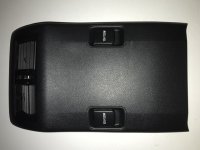
I got an idea to install LEDs in that rear facing panel of the center console to implement footwell lights. But I didn’t want them to shine forward directly into the passenger’s eyes. And I wanted a switch that can’t inadvertently get bumped with knees or feet. So here’s what I came up with:

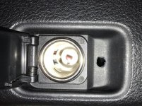
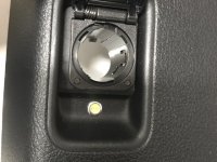
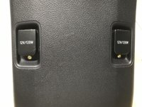
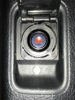
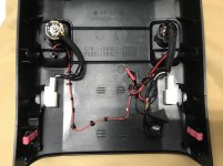
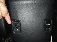
Two bright LEDs installed in the recess of the covered 12V outlets to provide shielded downward (only) light. And a circular latching push button switch to control them. Since I don’t need two outlets back there I gutted one outlet and used it to install a hidden, covered switch.
 

Attachments

  • B15EAD2C-09F7-4621-B6FE-9397CA78236F.jpeg
    B15EAD2C-09F7-4621-B6FE-9397CA78236F.jpeg
    118.2 KB · Views: 824
  • 9501C5E0-DECB-44D5-8EA3-DD8F127ED0EA.jpeg
    9501C5E0-DECB-44D5-8EA3-DD8F127ED0EA.jpeg
    76.8 KB · Views: 872
Register to hide this ad
Parts

Parts:
Two Oznium flush mount bolt LEDs, 6 mm, 1W, no lens, cool white, silver (could also get black housing).

LED Bolt Flush Mount Lights | Bright + 12 Volt | Oznium LEDs

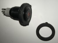
Oznium pushbutton on/ off switch with (red) LED dot.

Waterproof On/Off Push Switch 12v with LED - Stainless Steel

Solder, electrical tape, E6000 hobby adhesive, black foam scraps, a 1 inch garden hose rubber washer.

Tools:
Wire cutters, wire strippers, tweezers, needle- nose pliers, nut driver set, 6mm drill bit (also from Oznium), drill, heat shrink tubing of various sizes, heat gun.
 
Procedure:
1. Sit in the back seat and remove the center console back panel. It easily pops off by hand backwards toward you from the top, see the emmantik thread above.
2. Remove the two white power plugs for the 12V accessory outlets. Push in the tabs to release them. Now you can work on the panel on your bench.
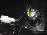
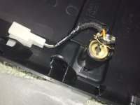
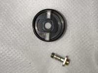
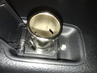
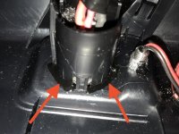
3. Choose a 12V outlet to sacrifice and with an appropriately sized nut driver remove the nut holding the outlet together. From inside of that outlet take out the threaded center stud and washer. With a large flat blade screwdriver inserted from the back into the slot of the metal inner sleeve of the outlet, twist it back and forth to work it out of the plastic shell. I did this to give myself plenty of room to install the switch and wiring. Save the sleeve just in case you ever want to re-assemble this outlet.
4. Re-assemble the other parts from the back of the outlet with the nut and screw. I then insulated them with electrical tape and taped that assembly to the plastic panel, down low and out of the way, once again just in case of the need to restore this outlet to original condition.
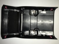
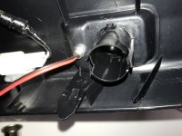
5. Drill a 6mm hole in the plastic in the middle of the recessed area under each outlet cover for the bolt LEDs. I drilled from the front; use a sharp point in the plastic to start the bit, drill slowwwly.
6. Install the LEDs flush, snug down the two nuts for each LED on the panel back side.
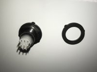
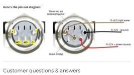
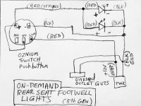
8. Solder wires (about 8 inches long) to the switch per the Oznium drawing. The wires and switch terminals are pretty small and delicate so take your time and insulate them with heat shrink tubing.
10. Fit the switch into the hose washer, or some other washer of the proper inner and outer diameter, and snug down the nut. Insert this into the outlet from the front and glue into place. On the other side I also packed the threaded side of the switch with plastic foam and tacked it in with adhesive to hold it all in place.
12. After the adhesive dries and the switch is snug in place, lay out your wiring, cut it to length, temporarily tape it into place for a clean look. Wire the LEDs in parallel and wire to the switch and power leads (twist leads together). Test your connections per the note below.
13. Solder the connections and insulate with tape and/or heat shrink. Refer to the Oznium drawing for the switch terminal configuration.
14. Clean up the wire routing, tape it down, spot tack it if desired.
15. Plug it back into the center console, turn on the ignition, and enjoy your on-demand footwell lights.
 

Attachments

  • 626B7300-853D-4B4F-A3EC-E0F47776A5E4.jpeg
    626B7300-853D-4B4F-A3EC-E0F47776A5E4.jpeg
    91.9 KB · Views: 794
  • 42953D7F-8E9C-4314-802D-02A3FF50D1BC.jpeg
    42953D7F-8E9C-4314-802D-02A3FF50D1BC.jpeg
    85.2 KB · Views: 774
  • 6CAA3300-ACC2-4C2E-AA8B-8027EA4FC7BA.jpeg
    6CAA3300-ACC2-4C2E-AA8B-8027EA4FC7BA.jpeg
    54.1 KB · Views: 768
  • DAA101B3-EBF0-474A-A7BF-4BD03A88897A.jpeg
    DAA101B3-EBF0-474A-A7BF-4BD03A88897A.jpeg
    78.7 KB · Views: 793
  • 48CC4553-238F-494B-9762-4DB0B3D7C61D.jpeg
    48CC4553-238F-494B-9762-4DB0B3D7C61D.jpeg
    114.2 KB · Views: 743
  • FD820703-5ADA-4636-A43B-0ECFE93B18FB.jpg
    FD820703-5ADA-4636-A43B-0ECFE93B18FB.jpg
    68.7 KB · Views: 763
  • F04F5BC5-FAD0-4DE5-A15D-43D9513A3434.jpeg
    F04F5BC5-FAD0-4DE5-A15D-43D9513A3434.jpeg
    109.5 KB · Views: 761
  • FD7B2B66-EB3F-4F2B-AD43-57AC73F79C6D.jpeg
    FD7B2B66-EB3F-4F2B-AD43-57AC73F79C6D.jpeg
    101.1 KB · Views: 768
Last edited:
More Photos
Edit: Corrected schematic to show switch (-) to GND connection (illuminates the switch LED).
 

Attachments

  • BAED9C08-21B2-4E75-A438-20FA1679ED72.jpeg
    BAED9C08-21B2-4E75-A438-20FA1679ED72.jpeg
    90.1 KB · Views: 722
  • DBCA26F9-BDE4-44D2-A6F0-16D08790ED3C.jpeg
    DBCA26F9-BDE4-44D2-A6F0-16D08790ED3C.jpeg
    45.9 KB · Views: 728
  • 2984300B-A2D3-4FE4-9DC1-89C703286F0C.jpeg
    2984300B-A2D3-4FE4-9DC1-89C703286F0C.jpeg
    40.2 KB · Views: 728
  • 039D5CF6-0DF6-44DE-8B6E-EA002DB32382.jpg
    039D5CF6-0DF6-44DE-8B6E-EA002DB32382.jpg
    71.6 KB · Views: 711
  • B2192A55-14D3-4076-921C-DDABC04264F5.jpeg
    B2192A55-14D3-4076-921C-DDABC04264F5.jpeg
    93.4 KB · Views: 408
Last edited:
And more photos. Modification complete.
 

Attachments

  • 936B40D2-0D24-48A3-A3D1-402833DAF12C.jpeg
    936B40D2-0D24-48A3-A3D1-402833DAF12C.jpeg
    125.4 KB · Views: 721
  • 40701B3D-652E-417D-9DD8-0B819711C400.jpg
    40701B3D-652E-417D-9DD8-0B819711C400.jpg
    67.8 KB · Views: 711
  • EE3A54E7-0A74-43AB-9799-14FBE2ED52C5.jpg
    EE3A54E7-0A74-43AB-9799-14FBE2ED52C5.jpg
    129 KB · Views: 724
  • 7FCC6DAA-0B41-4947-9DAA-2A64983C9889.jpeg
    7FCC6DAA-0B41-4947-9DAA-2A64983C9889.jpeg
    101.4 KB · Views: 703
Last edited:
Notes:
- The power leads to the outlet socket are +12 = white (center pin) and GND = black. But verify this with a voltmeter. Your colors may vary.

- I stripped wire inline from the power leads and soldered to them, but you could use wire taps on these larger gauge wires if you prefer. I don’t like wiretaps.

- All connections were soldered; the LED wires are too small a gauge to crimp or tap. When completed I spot-tacked the wires down into position with E6000 adhesive.

- There’s a lot of extra length of the red/black wire with the bolt LEDs. Use that for hook up wire to the switch. Once again, these are small gauge, small leads. Be careful and shrink tube/strain relieve them.

- The NC (normally closed) pin of the switch is not used. I clipped it off to make more room for wiring.

- By removing the guts from the plastic outlet housing (that now contains the switch) it was a little loose, so after everything was assembled I ran a bead of adhesive around the base of it to hold it in place.

- Before you solder everything and plug it back into the truck you can bench test your switch-LED connections and operation with a 9 volt battery.

- For insulating small wires and solder joints with electrical tape, cut thinner strips (1/4 inch or less) with a blade, to wrap around the joint, instead of using the typical 1/2 inch width tape.
 
Last edited:
That's pretty cool! I might have to give this a try! I have an unused socket so this may be a good time to give this a shot! Thanks for sharing!
 
And more photos. Modification complete.

This is great. Giving me some ideas towards what I've been thinking of trying to install as "dog lights" in the rear. Wouldn't necessarily work this exact way given when dog is in the back (and not in kennel) she sits in the low parts with rear seat flipped forward.

Thinking cap is on! Great write up.
 
I for one think its a great idea. I am tempted to buy that console to do it, since my '13 doesn't have those knockouts.

Those little recesses do make nice visors for the lights.

That back panel (Console panel rear 58923-35030) seems to be about $60. But I can’t tell from online drawings if it includes the power outlets. Probably have to see a dealer to check on the correct part number.
 
Those little recesses do make nice visors for the lights.

That back panel (Console panel rear 58923-35030) seems to be about $60. But I can’t tell from online drawings if it includes the power outlets. Probably have to see a dealer to check on the correct part number.


It does not include the power outlets.
 

Members online

Forum statistics

Threads
278,316
Messages
3,554,120
Members
248,016
Latest member
Advally Service

Trending content

Back
Top