Rear Axle Seal: Axle Puller Tool Design

nobb

New member
Hi guys,

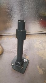
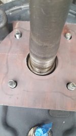
I know there are already a ton of threads on leaky rear axle seals, but I wanted this one to focus on the special tool needed to pull the axle shaft off the hub to replace the bearings.

I'm referencing the original axle seal how-to thread here:
http://www.toyota-4runner.org/3rd-g...e-information-replacement-thread-3rd-gen.html

AFAIK, the dimensions required for the special tool are (please verify these dimensions if I am wrong, or if the tolerances can be revised!):

4 holes, each 11 mm diameter and arranged in a square
89 mm hole-to-hole length
125 mm diagonal hole-to-hole length
75 mm center hole. Required to clear the retainer and ABS ring.
~0.6 meter length, from plate that secured to wheel hub to end of tool that rests on the hydraulic press fixed surface

There's some great designs, my favorite is the one where the guy incorporated a bearing puller to clamp the ABS ring such that both the ABS ring and retainer could be pulled off and re-used (instead of having to cut and chisel these parts off). However, all these designs are welded together, which is something the average backyard mechanic like me might not have access to.

I would be interested in hearing if anyone has successfully fabricated this tool from more easily sourced materials and fittings (eg. hardware/industrial supply store)? Or have you tried other methods of getting the axle off that worked? Ideally while keeping the retainer and ABS ring intact.

If so, please share your ideas!
 
Last edited:
Register to hide this ad
A Toyota Tech friend of mine had one made with Chromoly. I used it last year on another friends 96 4runner. It was very handy with the lowered weight when tossing the axle around in the press.
 
I would be interested in hearing if anyone has successfully fabricated this tool from more easily sourced materials and fittings (eg. hardware/industrial supply store)? Or have you tried other methods of getting the axle off that worked? Ideally while keeping the retainer and ABS ring intact.

If so, please share your ideas!

Here's how it's done on earlier axles w/o ABS.

https://www.4x4wire.com/toyota/maintenance/rear_axle/wheel_bearing/

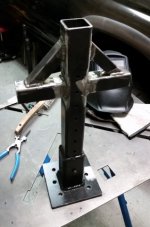
I couldn't get this to work on 3rd gen axles, I think maybe because of the added resistance of the ABS ring and second retainer? I ended up boogering this tool together from a piece of axle housing and a little square tube. Don't let lack of a welder stop you. A quality used 110v welder can be had for under $200, or your local classifieds are full of guys with welding rigs looking for sidework.

WP_20160406_18_21_44_Pro[1].jpg
 

Attachments

  • WP_20160406_18_21_44_Pro[1].jpg
    WP_20160406_18_21_44_Pro[1].jpg
    140.4 KB · Views: 6,130
I also see that most designs seem to use a welded pipe/square tube between the flange and the top part that seats onto the hydraulic press. I wonder if there is any reason why one couldn't use some strong wire rope somehow instead for the pulling force?
 
Sounds like you now have a good excuse to invest in a welder :D

There are pics in that thread of the tool I built. I was able to use a harbor freight #93980 bearing splitter set with it (I stole this idea from someone else).

For what its worth, here's a few dimensions:

Overall length from bottom of plate to top of tube is 19.375"

The plate is 6" x 6" x 3/8". I cut a 2" hole in the center, and then the 4X hole pattern for the axle studs. The axle stud holes are .433" dia, and spaced 3.486" apart (symmetrically around the 2" bore). Ignore the additional 2 holes in the plate. I was able to use 2 of the holes (diagonally) to attach the bearing splitter to.

The lower tube is a short section of 2.5" X 2.5" X ~1/4".

The upper portion of the tube is 2" X 2" X ~3/16".

I needed the larger tube at the bottom to have some clearance around the collars, and the smaller tube at the top to press the collars/reluctor rings back in.

The upper cross bars are 2" x 2" X 3/16. The bottom of the upper cross bars is 5.5" below the top of the vertical tube. The gussets are 1x1.

Most of it was just scabbed together from scraps I had from other projects.
 

Attachments

  • 20151030_190412_318x480.jpg
    20151030_190412_318x480.jpg
    42.8 KB · Views: 9,226
I'm starting to have a sense of how the removal will happen.

To press the ABS ring and retainer back onto the shaft, would using the bearing separator work or is another tool needed? eg. Flip the axle assembly such that the wheel hub points up and the axle points down. Rest the bearing retainer on the hydraulic press surface then press the wheel hub down via the press to force the retainer + ABS ring onto the bearing separator.

I'm still undecided if I should leave the retainer in the OEM spot or flipped as per DrCoffee's post here:

http://www.toyota-4runner.org/3rd-gen-t4rs/114743-possible-solution-leaking-axle-seals.html
 
To press the ABS ring and retainer back onto the shaft, would using the bearing separator work or is another tool needed?

You might be able to get away with using the press plates. If not, use a piece of pipe or tube, kinda like this:
 

Attachments

  • IMG_8309_1280x960_393x480.JPG
    IMG_8309_1280x960_393x480.JPG
    50.6 KB · Views: 5,991
I'm still undecided if I should leave the retainer in the OEM spot or flipped as per DrCoffee's post here:

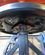
I took many of the same measurements he did, and came to the same conclusions. You can prove it to yourself with the grease test. Mine have been flipped for thousands of miles, and my ABS rings are nice and dry.
 

Attachments

  • dry_327x480.JPG
    dry_327x480.JPG
    37.3 KB · Views: 5,288
I'm starting to have a sense of how the removal will happen.

To press the ABS ring and retainer back onto the shaft, would using the bearing separator work or is another tool needed? eg. Flip the axle assembly such that the wheel hub points up and the axle points down. Rest the bearing retainer on the hydraulic press surface then press the wheel hub down via the press to force the retainer + ABS ring onto the bearing separator.

I'm still undecided if I should leave the retainer in the OEM spot or flipped as per DrCoffee's post here:

http://www.toyota-4runner.org/3rd-gen-t4rs/114743-possible-solution-leaking-axle-seals.html

I used a HF seal driver set to seat the new bearing in the backing plate. I could have rigged something to press the retainers and ABS ring on, but it was easier/quicker to drive them on with a piece of thick wall 2x2 tube. You can't hurt them. Either way you do it, you can't just run them on as far as they'll go, you need to be sure you get the depth of the ABS ring and second retainer just right.

And on that note, flip the second retainer. There's no reason not to, and if you get the depth of the ABS ring set and then flip the second retainer and put it right next to the ring then the seal should land exactly in the middle of the retainer seal riding surface.
 
So as an update, it looks like the leak has gotten worse so I'm going to have to tackle this job sooner than later. Although it's just one axle, I'm just going to re-do both. I think I'll try the flipped retainer (Dr.Coffee) method, just worried about getting it pressed on at the right place. It seems the tolerances are very tight for where this retainer has to go.

I'm using the OEM Toyota inner seal. Outer seal and bearing will be Timken, of which the bearing also comes with the two retainers. I figure Timken is a pretty reputable brand. As much as I like OEM parts, the dealers here in Canada charge an arm and a leg for them.

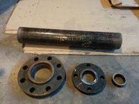
As for the tool, I was scrounging around the scrap metal bin at work (oilfield fabrication shop) and found just the right parts for the job. In theory, based on the measurements provided. The parts consist of:

1. 2"-150# slip on raised face flange. The 4 bolt pattern on this matches up exactly with the measurements on the Toyota hub. I am grinding down the raised face to get a flat seat.
2. 20cm long 3" schedule 40 pipe.
3. 3" threaded flange. This will be for the press end.
4. Small piece of 2" schedule 40 pipe section. This will be used to press on the new retainer and ABS ring.
5. Bearing puller tool which I will have to buy new. This will be attached to the hub end of the tool such that I can use this to pull off the existing ABS ring and retainer. The tool cost $30 and a new ABS ring costs $50 each, so it makes sense to reuse the part.

I think these parts should be pretty easy for people to find from an industrial supply/piping store.

I don't have a welder, so I am instead going to use two old batteries, some jumper cable, and a welding stick to put this all together. Probably won't be pretty but should work.

Any critiques, feel free to comment!
 

Attachments

  • IMG_20160424_184333.jpg
    IMG_20160424_184333.jpg
    131.4 KB · Views: 8,139
The tool worked great and my measurements were spot on. Used an adjustable bearing splitter which pulled the ABS ring and retainers off perfectly with no damage, so I reused them.
 
I took some 6" x 6" plate and welded up this one, kind of made it up as I went along but it works great !
 

Attachments

  • thumbnail (16).jpg
    thumbnail (16).jpg
    115.4 KB · Views: 889
  • thumbnail (6) - Copy.jpg
    thumbnail (6) - Copy.jpg
    65.8 KB · Views: 886
I posted this over in the Rear Axle Seals Ultimate Information Replacement Thread and am still wondering if anyone else thought of this.

(I removed the shoutouts to mtbtim)

----------------------------------------------------

As for the puller tool, I've gone back and forth on buying one or making one. I'm a cheap bastard and I like to make things, but the puller tool is one thing that I've had a hard time pulling the trigger on.

I've considered making something like this:
aT459Hz.jpg


nYbG4KK.jpg


But then the other day I saw another method that involved drilling a hole in the crossbar of the press:

P4QL4mJ.jpg


yfiMu6A.jpg


This got me thinking about another method that doesn't involve drilling into the press. Rather than doing that, I'm going to get two 3"x8" half-inch plates and drill a hole in the middle. Then you can put a long grade 8 bolt down through that and into the bearing case. The plates would cost me about $25, though it would require pounding the studs out as demonstrated by mtbtim in his video.

This is what prompted my previous question regarding the thread size and pitch of the four bolts on the bearing case. Now I'm thinking that the case isn't threaded, but the bolts would come down through the plate and get secured from behind. Kind of like this:

iYlrlUD.jpg


Anyone see anything wrong with this? The plates are 1/2" A36 hot rolled steel, so they would be plenty strong enough even at the full 20 ton capacity of the press. You could also use this setup with a bearing puller to remove the abs tone ring as well.

I've got the press sleeves that mtbtim has, so getting everything back together isn't a big deal.
 
I agree. You don’t need anything crazy. And that tool will work with a abs ring. Me and my friend made one while back out of 4x4 tube and some plate. Then we torched the hole pattern.
 

Members online

Forum statistics

Threads
278,311
Messages
3,554,082
Members
248,016
Latest member
Advally Service

Trending content

Back
Top