

rigtec
New member
Hey team,
I know those of you who participated in the 'Group buy' are really looking fwd to seeing that carton on your doorstep, as you should be! My 270-XP has been in for two (trouble free) years now, but I remember being anxious waiting for about six weeks for it to arrive; back then these alternators were made to order; hence the extended arrival time! Even though I've had my new power plant and grid in for a good while now, I want to be around for those of you who may be doing a H.O. alternator swap and 'BIG THREE' for the very first time.
It's not complicated or very difficult at all, but there are some precautions that I thought to make you aware of to spare you of any unnecessary expense or electrical failures before you start the work! All you'll need to do the cable size increase (big three) is to add Three 19", 4ga stud to stud (looped) cables; one 19 inch POS cable, and two 19 inch NEG cables. There are different procedures to getting it done and I don't want you to exchange your own better judgement for mine, but here's just one of the ways that works!
As far as the heavier gauge cable positions... they will run in parallel with the existing factory 'under sized' cables to lower the electrical path resistance, direct the auxiliary (aftermarket) load 'away from the OEM fuseboxes and main current carrying lines'. I know that there are some that don't understand how you can add a larger alternator and additional high current accessories and NOT change the amount of amperage running through the factory wiring and fuseboxes...
The reason that your aftermarket electrical equipment won't draw from the factory power grid is because of the way the new accessories are grounded and fed. We're not connecting any additional loads to the OEM fuseboxes or it's associated wiring. Our new equipment has it's own power source (Alternator output B-term) and our new designated heavy duty ground points... "see the factory wiring scheme and our own low resistance wiring plot below":
FACTORY WIRING SCHEME
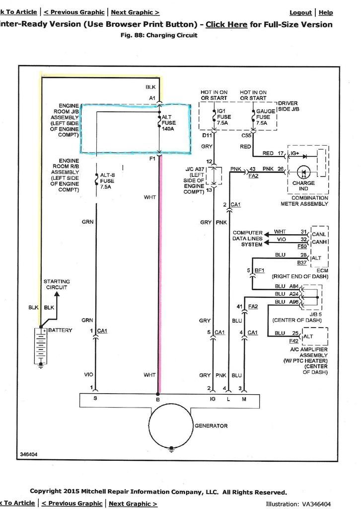
As you can see, the stock wiring goes from the alternator, enters the main Rly/fusebox, and then on to the battery. The problem is that by time the battery receives any electrical reward for it's faithful service, the current may already be totally used up; depending on the amount of load consumed by the stock accessories... not good for an alternator that may be running at full field; full field is a term that means that the alternator's rotor is generating the max electro-magnetic field that it possibly can, and so the stator (the place where the high output current is generated), has absolutely reached it's full rated output and the high heat has now become a major factor! Below is an over simplified diagram of a (Dotted) line (Line-C) that we'll add to the circuit to help minimize the current that runs through the main fusebox, the system 140A fuse, and to assure that the battery has an equal opportunity to receive a nominal charge; but that really can't happen if the alternator doesn't have enough capacity to meet it's demand!
So here's where the H.O. alternator becomes essential. Now we're doubling the capacity of our power plant which will (should) have more than enough capacity to meet the needs of the factory electrical system, charge the battery, and... still have enough to power to take on your aftermarket accessories as well!

"Oh... An Important Notice"
To those of you who are planning on implementing a fuse in the Quick Charging cable between the B+ Alternator output terminal and the POS + battery terminal... Be very careful! Should that Quick charge line fuse blow while in operation, that High current that's flowing through that line will suddenly change direction and flow through the ONLY electrical path available; which is the OEM line through the MAIN fusebox.
This extra current will then surge through the 140A main fuse and likely take it out (Blown main fuse); which as you know is a major project to replace! I've decided to remove my quick charge line-fuse/Breaker all together so there's no chance of causing the main fuse to blow. It doesn't really matter anyway unless there is a catastrophic front-end crash which is the reason the OEM 140A fuse is there; my inline fuse was only there to follow/observe the factory safety protocol! This isn't the only un-fused power line in the vehicle; the hardwired line cable that goes directly from the battery to the starter has no fuse either so there's really no anticipated danger in leaving these lines un-fused.
If it gives you any more comfort to install a very high amperage (270A) breaker or a manual disconnect between the battery and the main output term at the alternator B+ term as a means of disconnecting in a hurry then feel free to do so; I've removed my aux charging line-fuse about two years ago, when I realized the potential problem of having that fuse/bkr in that line! Again... I don't want you to relinquish your own judgement for mine, I just wouldn't want to blow that OEM 140A fuse as a result of an oversight on my part!
WITH INLINE SAFETY FUSE

WITH INLINE SAFETY FUSE REMOVED

Here's a couple of links that I find very informative wrt the big three, the first is from JL Audio a company that I think most of you are familiar with: https://jlaudio.zendesk.com/entries/21923235-Upgrading-the-Big-3-
...and then another tutorial thread by Steve Meade Design; another reputable source of information that you may also find helpful:
https://www.google.com/url?sa=t&rct...KrmJULsz-dafBjBeQ&sig2=m1YM7f9uGfsuT_Qx6yqYVw
The cables that I used in parallel are exactly like the ones in the photo below; their price was about $10-$12 bucks each at AutoZone but I've seen them on ebay for $8 dollars for a set of two!

I wish you all the best success with your new 270-XP H.O. alternator installs and parallel (big three) cables; I know you won't ever be sorry you invested into a large enough electrical system for your modified 4Runners,
rig, Cheers!
I know those of you who participated in the 'Group buy' are really looking fwd to seeing that carton on your doorstep, as you should be! My 270-XP has been in for two (trouble free) years now, but I remember being anxious waiting for about six weeks for it to arrive; back then these alternators were made to order; hence the extended arrival time! Even though I've had my new power plant and grid in for a good while now, I want to be around for those of you who may be doing a H.O. alternator swap and 'BIG THREE' for the very first time.
It's not complicated or very difficult at all, but there are some precautions that I thought to make you aware of to spare you of any unnecessary expense or electrical failures before you start the work! All you'll need to do the cable size increase (big three) is to add Three 19", 4ga stud to stud (looped) cables; one 19 inch POS cable, and two 19 inch NEG cables. There are different procedures to getting it done and I don't want you to exchange your own better judgement for mine, but here's just one of the ways that works!
As far as the heavier gauge cable positions... they will run in parallel with the existing factory 'under sized' cables to lower the electrical path resistance, direct the auxiliary (aftermarket) load 'away from the OEM fuseboxes and main current carrying lines'. I know that there are some that don't understand how you can add a larger alternator and additional high current accessories and NOT change the amount of amperage running through the factory wiring and fuseboxes...
The reason that your aftermarket electrical equipment won't draw from the factory power grid is because of the way the new accessories are grounded and fed. We're not connecting any additional loads to the OEM fuseboxes or it's associated wiring. Our new equipment has it's own power source (Alternator output B-term) and our new designated heavy duty ground points... "see the factory wiring scheme and our own low resistance wiring plot below":
FACTORY WIRING SCHEME

As you can see, the stock wiring goes from the alternator, enters the main Rly/fusebox, and then on to the battery. The problem is that by time the battery receives any electrical reward for it's faithful service, the current may already be totally used up; depending on the amount of load consumed by the stock accessories... not good for an alternator that may be running at full field; full field is a term that means that the alternator's rotor is generating the max electro-magnetic field that it possibly can, and so the stator (the place where the high output current is generated), has absolutely reached it's full rated output and the high heat has now become a major factor! Below is an over simplified diagram of a (Dotted) line (Line-C) that we'll add to the circuit to help minimize the current that runs through the main fusebox, the system 140A fuse, and to assure that the battery has an equal opportunity to receive a nominal charge; but that really can't happen if the alternator doesn't have enough capacity to meet it's demand!
So here's where the H.O. alternator becomes essential. Now we're doubling the capacity of our power plant which will (should) have more than enough capacity to meet the needs of the factory electrical system, charge the battery, and... still have enough to power to take on your aftermarket accessories as well!

"Oh... An Important Notice"
To those of you who are planning on implementing a fuse in the Quick Charging cable between the B+ Alternator output terminal and the POS + battery terminal... Be very careful! Should that Quick charge line fuse blow while in operation, that High current that's flowing through that line will suddenly change direction and flow through the ONLY electrical path available; which is the OEM line through the MAIN fusebox.
This extra current will then surge through the 140A main fuse and likely take it out (Blown main fuse); which as you know is a major project to replace! I've decided to remove my quick charge line-fuse/Breaker all together so there's no chance of causing the main fuse to blow. It doesn't really matter anyway unless there is a catastrophic front-end crash which is the reason the OEM 140A fuse is there; my inline fuse was only there to follow/observe the factory safety protocol! This isn't the only un-fused power line in the vehicle; the hardwired line cable that goes directly from the battery to the starter has no fuse either so there's really no anticipated danger in leaving these lines un-fused.
If it gives you any more comfort to install a very high amperage (270A) breaker or a manual disconnect between the battery and the main output term at the alternator B+ term as a means of disconnecting in a hurry then feel free to do so; I've removed my aux charging line-fuse about two years ago, when I realized the potential problem of having that fuse/bkr in that line! Again... I don't want you to relinquish your own judgement for mine, I just wouldn't want to blow that OEM 140A fuse as a result of an oversight on my part!
WITH INLINE SAFETY FUSE

WITH INLINE SAFETY FUSE REMOVED

Here's a couple of links that I find very informative wrt the big three, the first is from JL Audio a company that I think most of you are familiar with: https://jlaudio.zendesk.com/entries/21923235-Upgrading-the-Big-3-
...and then another tutorial thread by Steve Meade Design; another reputable source of information that you may also find helpful:
https://www.google.com/url?sa=t&rct...KrmJULsz-dafBjBeQ&sig2=m1YM7f9uGfsuT_Qx6yqYVw
The cables that I used in parallel are exactly like the ones in the photo below; their price was about $10-$12 bucks each at AutoZone but I've seen them on ebay for $8 dollars for a set of two!

I wish you all the best success with your new 270-XP H.O. alternator installs and parallel (big three) cables; I know you won't ever be sorry you invested into a large enough electrical system for your modified 4Runners,
rig, Cheers!
Last edited:


