Wiring for Light Bar

Travtaz997

New member
Hi all,
I'm planning to wire up my 41.5in LED Light bar in my roof rack pretty soon. I'm confused on exactly how to wire it. I know where I'm going to put it and how to run the wires but I'm not sure how I tap into a power source etc.

I have a 12v relay, switch, switch wire plug and instructions from AirOnBoard. One of the the wires on the switch wires (blue) is to light up the switch when my dash lights are on. It says "connect this pin to your cars dash / parking light circuit". So does this mean I find the wire to my dash lights and splice into it? Or is there an open fuse spot where I can connect a wire fuse?

Same for getting the actual battery power to the relay - do I just plug a male disconnect terminal into a certain female plug in the engine bay fuse box that provides constant 12v?


I apologize for the noobish questions :(. I can do the electrical work, I just don't know where to get the power ..
 
Register to hide this ad
I got my power constant from battery for the relay, keyed power from fuse tap inside I think its my seat or something I know I'd notice if it went out. Then grounds.


I used this wiring diagram to help me.

foglite_zps5e0b3a1d.jpg~320x480
 
Last edited:
I got my power constant from battery for the relay, keyed power from fuse tap inside I think its my seat or something I know I'd notice if it went out. Then grounds.


I used this wiring diagram to help me.

foglite_zps5e0b3a1d.jpg~320x480

I think that [MENTION=99949]Travtaz997[/MENTION] is referring to how to power the AIRONBOARD switch's "built in" LED light, rather than the light bar itself. Travtaz997, I installed three of the AIRONBOARD switches in my center console, to control all of my LED light bars, etc. I spliced the blue wire into the lighting for my cup holders and all is well! Are you installing your switches in the dash or the center console? You have several options for splicing with either location. Let me know if you need any more help!
 
I think that [MENTION=99949]Travtaz997[/MENTION] is referring to how to power the AIRONBOARD switch's "built in" LED light, rather than the light bar itself. Travtaz997, I installed three of the AIRONBOARD switches in my center console, to control all of my LED light bars, etc. I spliced the blue wire into the lighting for my cup holders and all is well! Are you installing your switches in the dash or the center console? You have several options for splicing with either location. Let me know if you need any more help!

[MENTION=89791]preacher35[/MENTION] I'm installing the switch in the dash to the left of the steering wheel. I wanted to avoid slicing and splicing into any wires haha. I will if I need to but do you know if there is a fuse in that fuse box right below the switches that I can replace with a Fuse Tap for the blue wire?

And I am looking for direction on how to power both. So I have my relay that I'll mount in my engine bay. I run a wire from ???? and connect it to the 30 terminal of the relay. Straight from the battery terminal or a slot in the fuse box in the engine bay?


Thanks [MENTION=87687]LTDSC[/MENTION] for the info and diagram. That does help.
 
[MENTION=89791]preacher35[/MENTION] I'm installing the switch in the dash to the left of the steering wheel. I wanted to avoid slicing and splicing into any wires haha. I will if I need to but do you know if there is a fuse in that fuse box right below the switches that I can replace with a Fuse Tap for the blue wire?

And I am looking for direction on how to power both. So I have my relay that I'll mount in my engine bay. I run a wire from ???? and connect it to the 30 terminal of the relay. Straight from the battery terminal or a slot in the fuse box in the engine bay?


Thanks [MENTION=87687]LTDSC[/MENTION] for the info and diagram. That does help.

[MENTION=99949]Travtaz997[/MENTION], yes, there are fuses that you can use a "fuse tap" or "add-a-fuse", but the problem with this is that you will have a constant power supply (and it doesn't matter which fuse you try they will ALL provide constant power) to the LED in the switch. In other words, the LED will be on FULL TIME, as opposed to only when you have the headlights on. Of course, either way is fine, per your want. I preferred to have mine on only when the headlights are on as the LED is too faint to see during day time anyway. I had absolutely no qualms about splicing into an existing wire. I did, however, add a convenient "connector" to make removal much easier, in case I ever get a wild hair up my ass. That being said, if you do opt to tap into an existing wire, a couple of convenient ones that you could utilize are the dimmer dial to the left of your switch OR the light for the rear window up/down switch to the right of the steering wheel. Hope that helps!
 
Last edited:
[MENTION=99949]Travtaz997[/MENTION], yes, there are fuses that you can use a "fuse tap" or "add-a-fuse", but the problem with this is that you will have a constant power supply (and it doesn't matter which fuse you try they will ALL provide constant power) to the LED in the switch. In other words, the LED will be on FULL TIME, as opposed to only when you have the headlights on. Of course, either way is fine, per your want. I preferred to have mine on only when the headlights are on as the LED is too faint to see during day time anyway. I had absolutely no qualms about splicing into an existing wire. I did, however, add a convenient "connector" to make removal much easier, in case I ever get a wild hair up my ass. That being said, if you do opt to tap into an existing wire, a couple of convenient ones that you could utilize are the dimmer dial to the left of your switch OR the light for the rear window up/down switch to the right of the steering wheel. Hope that helps!

That is exactly what I needed to know. Thank you so much. Now I just need to figure out how to get the power from the battery.
 
Haha maybe every time I wanna turn my light on I'll just lick both thumbs, touch one to the battery and the other to the light.

The diagram [MENTION=87687]LTDSC[/MENTION] gave you is perfect - it's easy:

tap + from a dash light source for AOB switch LED
tap + fused IGN source (fuse box or similar, doesnt matter what you tap its just for relay trigger)
run that wire to switch input
run switch output to pin 86 on relay
run + 12g wire from battery ti pin 30 on relay
run + 12g from pin 87 to your accessory (light bar)

run -12g wire negative for your accessory (ground the light bar)
run ground for the relay to pin 85
run ground for the AOB switch on the body inside somewhere

blind ******* drivers.
 
That is exactly what I needed to know. Thank you so much. Now I just need to figure out how to get the power from the battery.

OK, [MENTION=99949]Travtaz997[/MENTION], for your direct power to the switch (although, I am assuming that you are using a relay as well, right?) you can use an ADD-A-FUSE if you like as you want power at the switch to direct the relay, full time. Being that you are using a relay, the actual switch will not draw much amperage anyway.
 
OMG.

Can we start over and ask a few simple questions first?

Picture of said switch and how you want it working.

How do you want the lights to work, all the time or only when ignition is on?

Switch, can it be illuminated with parking lights ?

Does it illuminate when it is on, like with a brighter led?

All these questions will dictates how it will be wired.
 
OMG.

Can we start over and ask a few simple questions first?

Picture of said switch and how you want it working.

How do you want the lights to work, all the time or only when ignition is on?

Switch, can it be illuminated with parking lights ?

Does it illuminate when it is on, like with a brighter led?

All these questions will dictates how it will be wired.

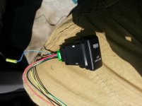
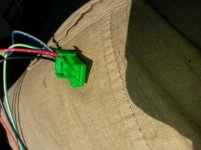
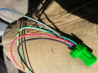
This is my switch, complete with wire harness;
12 Volt 3amp ON-OFF Toyota OEM Replacement Push Switch LED LIGHT BAR BLUE -Air On Board

The backlight on the switch should come on with dash lights. The actual light bar should come on whenever the button is pushed, whether or not the key is in.
 
Crap, that's all they gave you?

Assumptions

Red will be constant power
Black will be ground
The other two
One would be output and one would be the positive from the dimmer circuit. Essentially tap to positive from one of the other switches when the lights come on. Iirc, is a green with red on the oem wires.

I would need you to find out the wiring on the switch. So I could tell you how to proceed.
 
Crap, that's all they gave you?

Assumptions

Red will be constant power
Black will be ground
The other two
One would be output and one would be the positive from the dimmer circuit. Essentially tap to positive from one of the other switches when the lights come on. Iirc, is a green with red on the oem wires.

I would need you to find out the wiring on the switch. So I could tell you how to proceed.

Relax, Aironboard sends a complete wiring diagram with their switches and it is extremely easy to read and interpret. [MENTION=99949]Travtaz997[/MENTION], if you DID NOT receive said wiring diagram, PM me and I will forward you a PDF of it.
 
Last edited:
Relax, Aironboard sends a complete wiring diagram with their switches and it is extremely easy to read and interpret. [MENTION=99949]Travtaz997[/MENTION], if you DID NOT receive said wiring diagram, PM me and I will forward you a PDF of it.

I did get the diagram from AOB so I'm good there. I know what the wires are, I just don't know where to attach them.

Black - Ground
Blue - Switch Backlight ---- DONE (Tapped into hazard button light)
Red - 86 pin of relay
Green - Power Lead

Relay;
85 - Ground
87 - Directly to light
86 - Red wire from switch
30 - Battery


Soooo the green wire on the switch I need to connect to....?
And the 30 terminal I'll just run a wire from the positive battery terminal
 
I did get the diagram from AOB so I'm good there. I know what the wires are, I just don't know where to attach them.

Black - Ground
Blue - Switch Backlight ---- DONE (Tapped into hazard button light)
Red - 86 pin of relay
Green - Power Lead

Relay;
85 - Ground
87 - Directly to light
86 - Red wire from switch
30 - Battery


Soooo the green wire on the switch I need to connect to....?
And the 30 terminal I'll just run a wire from the positive battery terminal

Green needs a + input to trigger the relay. Fuse box or a tap another circuit since it's such a low draw
 
Today I finally found some time to work on the wiring. I successfully wired the relay and switch, but have yet to mount my bar because I haven't fabricated the brackets for it yet. But I did test my light and it worked, albeit not very bright, but I'm just glad it worked. I'll probably have to redo some wires.

My light is 240 Watts. I used 12g wire from the battery (inline fuse) to the 30 relay terminal and also from the 87 terminal to the light. I believe I used a different gauge for the other wires. Any idea why the light is so dim? I'll have to check and see if I used 12g for the relay ground, not entirely sure.

Thanks [MENTION=89791]preacher35[/MENTION] and [MENTION=55855]zopperman[/MENTION] for the help, and having to really 'dumb it' down for me :).
 

Members online

Forum statistics

Threads
278,309
Messages
3,554,068
Members
248,016
Latest member
Advally Service

Trending content

Back
Top