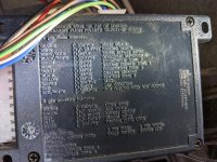
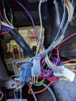
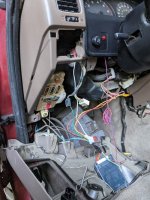
2001 SR5 Wiring Mess

Deej101

New member
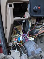
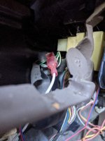
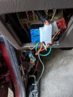
I know this is a long shot, but can anyone offer a preliminary prognosis on how much headache I'm in for?

I knew this car had wiring issues when I acquired it, but now is the first time I'm finally tackling it. I know next to nothing about electrical, but want to learn.

As far as symptoms, the alarm system is so screwy that I don't even use it (but would like to). I suspect a lot of this mess involved a home-done sound system, which I don't care about at all. The antenna was broken and I've already removed it. The speaker wiring was so messy that I've already cut all of them.

But a bunch of the interior lighting has never worked, and the door-ajar ding never worked.

If you were me, where would you start in trying to untangle this mess (besides taking it to a shop)?

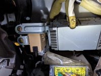
Are there any components that are obviously for the sound system that I can safely remove to simplify figuring out the alarm and lighting issues?

Any advice/input greatly appreciated.
 

Attachments

  • PXL_20210815_010616336_1_1.jpg
    PXL_20210815_010616336_1_1.jpg
    108.9 KB · Views: 294
  • PXL_20210815_011046351_1_1.jpg
    PXL_20210815_011046351_1_1.jpg
    122.7 KB · Views: 315
  • PXL_20210815_010837822_1.jpg
    PXL_20210815_010837822_1.jpg
    123.7 KB · Views: 285
  • PXL_20210815_010848704_1.jpg
    PXL_20210815_010848704_1.jpg
    94.6 KB · Views: 267
  • PXL_20210814_233715001_1.jpg
    PXL_20210814_233715001_1.jpg
    85.9 KB · Views: 290
Register to hide this ad
I know this is a long shot, but can anyone offer a preliminary prognosis on how much headache I'm in for?

I knew this car had wiring issues when I acquired it, but now is the first time I'm finally tackling it. I know next to nothing about electrical, but want to learn.

As far as symptoms, the alarm system is so screwy that I don't even use it (but would like to). I suspect a lot of this mess involved a home-done sound system, which I don't care about at all. The antenna was broken and I've already removed it. The speaker wiring was so messy that I've already cut all of them.

But a bunch of the interior lighting has never worked, and the door-ajar ding never worked.

If you were me, where would you start in trying to untangle this mess (besides taking it to a shop)?

Are there any components that are obviously for the sound system that I can safely remove to simplify figuring out the alarm and lighting issues?

Any advice/input greatly appreciated.

(little off topic i apologize) but how'd you get the antenna out? was it easy? i need to disable the motor in mine so it stops going up when i'm using usb.


Sent from my iPhone using Tapatalk
 
(little off topic i apologize) but how'd you get the antenna out? was it easy? i need to disable the motor in mine so it stops going up when i'm using usb.


Sent from my iPhone using Tapatalk

Getting the whole antenna out is not necessarily "easy" (my main difficulty was in getting the wire out), and I posted in this thread about it somewhat:

https://www.toyota-4runner.org/3662241-post14.html

Can't you just disconnect it to stop it?
 
yeah, i just didn't know what to disconnect other than the motor itself.
Sent from my iPhone using Tapatalk

The connector is behind your passenger wheel well. It's easy to get to, just remove the plastic wheel well cover (one 10mm bolt and a bunch of plastic clips). It's even easier if you also remove a few fender bolts so you can move the fender a little.
 
good grief! Gotta admire the persistence there. Your previous owner seemed to think he had better ideas then Toyota and did it with a lot of wire. A couple of thoughts. Since adding aftermarket stereo is trivial with a proper harness I would trace anything that goes to the center dash and is connected to the new stereo and then pull it. Hoping the previous person left the exisitng plugs so you can fix that section pretty easily. Your reall issue is the alarm. Messing that up may kill the ability to start and you said you are not expereinced with electrical. I would look at paying a local alarm shop to undo it - that way you have some fallback if they screw it up. I would not touch that without a Toyota wiring diagram and a diagram for the alarm
 
good grief! Gotta admire the persistence there. Your previous owner seemed to think he had better ideas then Toyota and did it with a lot of wire. A couple of thoughts. Since adding aftermarket stereo is trivial with a proper harness I would trace anything that goes to the center dash and is connected to the new stereo and then pull it. Hoping the previous person left the exisitng plugs so you can fix that section pretty easily. Your reall issue is the alarm. Messing that up may kill the ability to start and you said you are not expereinced with electrical. I would look at paying a local alarm shop to undo it - that way you have some fallback if they screw it up. I would not touch that without a Toyota wiring diagram and a diagram for the alarm

Thanks for the reply. Of course, that's sound advice re: the alarm system, will almost surely eventually happen. However, in the meantime, I'd like to understand what I'm looking at. I won't alter anything unless I'm certain of what I'm doing, so there shouldn't be much risk in just trying to figure out what this mess represents. Know what I mean? Compulsively curious, I guess.
 
Unless you're really trying to repair some of the things mentioned amiss, I'd leave it alone.

Cut more than one wire and stuff goes worse can then become difficult to figure out what did what. But if you've got the cash and desire to clean it up, I don't really think its that far off toyota spec just on looks. Luck no matter what ya' do.
 
I have a bit of experience with messy wiring because the previous owner fitted at least 3 additional circuits throughout my car and didn't label any of them, and I removed 18 feet of wiring and installed a kill switch. Your probably in for a bit of a headache.

The best way to definitively figure out which wires go to the home done sound system is to take continuity of the wires leading out of the fuse box to see if they connect to the speakers so you know which ones can be removed. The other method is to pull up trim and follow the wires back, I did this too and it wasn't super difficult but it can be time consuming and you risk breaking trim or the clips that hold them in.

After market alarm systems seem to always be problematic, and I personally wouldn't keep it. But the best way to trouble shoot it is to find out where the wires to it go and if they are still connected properly, only after then would I start measuring voltages if nothing is found.

I wouldn't be surprised if the poorly done mods are also causing issues with the stock electrical circuits because poorly done electrical work has a way of also screwing up other stuff as well.

To fix the issues with lighting and door checkers (after checking the fuses) I would do the same thing as before. Take continuity from the known fuse location of that circuit and make sure it still is connected to the end. If it doesn't have continuity then follow the wire up until you find an issue. If it does have continuity then check the voltage values and investigate whether you have bulbs that are burned out.
 
Most wires for an alarm will just tap into something and should be fairly trivial to remove. Everywhere there is/was a t-tap should be inspected and repaired if the copper is damaged (cut, strip, solder and heat shrink if necessary). The only big one will be the starter interrupt. That should be easy to find, as it will be the thickest and the only 'cut' wire in the whole setup.

Just take it 1 wire at a time and you'll get there. Repair anything questionable with a good solder joint or a high quality crimp.

-Charlie
 
I have a bit of experience with messy wiring because the previous owner fitted at least 3 additional circuits throughout my car and didn't label any of them, and I removed 18 feet of wiring and installed a kill switch. Your probably in for a bit of a headache.

The best way to definitively figure out which wires go to the home done sound system is to take continuity of the wires leading out of the fuse box to see if they connect to the speakers so you know which ones can be removed. The other method is to pull up trim and follow the wires back, I did this too and it wasn't super difficult but it can be time consuming and you risk breaking trim or the clips that hold them in.

After market alarm systems seem to always be problematic, and I personally wouldn't keep it. But the best way to trouble shoot it is to find out where the wires to it go and if they are still connected properly, only after then would I start measuring voltages if nothing is found.

I wouldn't be surprised if the poorly done mods are also causing issues with the stock electrical circuits because poorly done electrical work has a way of also screwing up other stuff as well.

To fix the issues with lighting and door checkers (after checking the fuses) I would do the same thing as before. Take continuity from the known fuse location of that circuit and make sure it still is connected to the end. If it doesn't have continuity then follow the wire up until you find an issue. If it does have continuity then check the voltage values and investigate whether you have bulbs that are burned out.

Thanks; good advice; I have no issues with removing any/all trim, lol--most of the truck interior is already in pieces. Today I will remove the door panels to get all the speaker wire removed. Plus, I'm deep cleaning as I go; the amount of dust and dirt I'm finding is incredible!

I'm very new to doing anything electrical, but have been YouTubeing quite a bit. I know basically how to test continuity, although knowing which places to touch and how, am still working out.

Here's a question: is this silver thing an amplifier, and can (should?) I remove it? I'm assuming the yellow box below it is part of the SRS system, yes? (pic shows behind center dash, below where radio goes)
 

Attachments

  • PXL_20210816_013133040_1.jpg
    PXL_20210816_013133040_1.jpg
    62.4 KB · Views: 255
Most wires for an alarm will just tap into something and should be fairly trivial to remove. Everywhere there is/was a t-tap should be inspected and repaired if the copper is damaged (cut, strip, solder and heat shrink if necessary). The only big one will be the starter interrupt. That should be easy to find, as it will be the thickest and the only 'cut' wire in the whole setup.

Just take it 1 wire at a time and you'll get there. Repair anything questionable with a good solder joint or a high quality crimp.

-Charlie
Yeah, seeing those "taps" everywhere. Not familiar--yet--with how they work or how to remove them. I did disconnect the "black box" (pic) to examine it. I found about a foot of a loose black wire that was probably the clipped starter wire. Lots of mess to untangle still. After I get all the sound system parts removed, I'll reconnect the battery and see if somehow the alarm system functions properly, before I commit to fully removing it, I suppose.
 

Attachments

  • PXL_20210816_002003640_1.jpg
    PXL_20210816_002003640_1.jpg
    81.8 KB · Views: 253
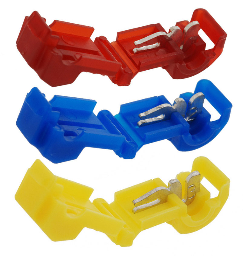
Yeah, seeing those "taps" everywhere. Not familiar--yet--with how they work or how to remove them.
There are many types, but they all work (ideally) by cutting the insulation and crimping a small "Y" connector around the wire.

t-taps.jpg


The main problem is that they can also cut the wire itself (the copper), then can be flakey (make bad contact), etc. They will also leave a weak spot in the wire if removed due to the cut insulation.

-Charlie
 
There are many types, but they all work (ideally) by cutting the insulation and crimping a small "Y" connector around the wire.

t-taps.jpg


The main problem is that they can also cut the wire itself (the copper), then can be flakey (make bad contact), etc. They will also leave a weak spot in the wire if removed due to the cut insulation.

-Charlie

Got it, thanks. Is there something like a glue (not glue, but is applied like it) that I could just drip onto the wire spot (after removing the Y connector) before rewrapping the wire? Reason is I don't trust myself with a soldering iron working in that tight space with all those wires around. I know such a product exists, does anyone know what I mean, and have used it?
 
Got it, thanks. Is there something like a glue (not glue, but is applied like it) that I could just drip onto the wire spot (after removing the Y connector) before rewrapping the wire? Reason is I don't trust myself with a soldering iron working in that tight space with all those wires around. I know such a product exists, does anyone know what I mean, and have used it?

If you really don't want to deal with cutting and soldering the wire, you can just wrap it in electrical tape. Liquid electrical tape does also exist, but is messy. If you aren't comfortable soldering, but want something a little better than electrical tape, you can cut the wire fully in the location the tap was, strip both ends back and use a butt connector. The next best option would be using a self solder butt connector which is basically shrink wrap with a solder ring in the center and adhesive rings on on both ends. You cut and strip the wires, slide the connector over one end, give the wires a quick twist to hold them and slide the connector back so the solder covers the part where the wires are connected and use a heat gun to shrink the tube and melt the solder.
 
If you really don't want to deal with cutting and soldering the wire, you can just wrap it in electrical tape. Liquid electrical tape does also exist, but is messy. If you aren't comfortable soldering, but want something a little better than electrical tape, you can cut the wire fully in the location the tap was, strip both ends back and use a butt connector. The next best option would be using a self solder butt connector which is basically shrink wrap with a solder ring in the center and adhesive rings on on both ends. You cut and strip the wires, slide the connector over one end, give the wires a quick twist to hold them and slide the connector back so the solder covers the part where the wires are connected and use a heat gun to shrink the tube and melt the solder.
Oh, I like that last thing you mentioned. Off to Amazon! Thanks!
 
I know such a product exists, does anyone know what I mean, and have used it?
I have used liquid electrical tape (I always have a bottle in my electrical kit) - though it can be messy like Skulking said (mostly because it takes a while to set up solid).

You only need to repair the wire if it was damaged by the tap. Otherwise, you just just need to make sure you re-insulate in whatever way you feel comfortable (electrical tape or liquid electrical tape).

-Charlie
 
I've used liquid electrical tape, I use it in my preferred method of joining wires together. When I needed to add my kill switch I would splay the ends of the wires together, apply solder and have it run between the wires for best connection, and then I would use liquid electrical tape to waterproof the solder point. It is a reliable and long lasting way of doing things, but the liquid electrical tape is messy because it never stops dribbling so you have to put something underneath the wires you will be using it on.
618DyILIPVL._SL1000_.jpg

Another way of joining wires together is a spade connector (seen above). It is often used to join wires to the back of switches (OEMs use it too), but you can also use it to join two wires together. The downside is that you have to crimp it, which can take a bit of practice, and the connection isn't waterproof (there are spade connectors that use heat shrink but they aren't as common).
WirefyBHT250-150_06_08860b8b-ca9a-4cf5-b0ac-163d02f42ea1@2x.jpg

The last connection type commonly used in automotive electrical use is the butt connector. These connectors come in two variety, crimp or solder, but they accomplish the same thing. The butt connector is a tube of heat shrink with some way of joining the wires in the middle.

On the crimp kind (seen above) you have to shove the bare copper end of a wire into a metal tube in the middle of the connection, you then use a crimping tool to crush the metal tube down onto the wires to hold them in place an make a connection. You then heat the heat shrink to make the connection waterproof and stronger. I am not the best at crimping so I try and avoid this kind unless necessary.

The solder kind of butt connector is simpler to use, you push the 2 exposed copper wires together in the middle where there is a ring of solder, as you heat the heat shrink the solder will liquify and join the wires together. I don't use this kind because you cant make the solder flow in-between the wires, so the result isn't as ideal (this point is illustrated in this video).

Whatever connector you prefer is really a personal taste. All that matters is that in insulates the wires at the connection to prevent an unwanted path to ground, is reliable enough to hold up to years of vibration, and it should really be water proof. I discourage the method of twisting two wires together and using electrical tape to insulate them, its lazy, unreliable, and not waterproof. Not to be confused with wire wrapping on a PCB, that method is very sound but sadly now obsolete (below).
zMDLT45.jpeg
 
Last edited:
To fix the issues with lighting and door checkers (after checking the fuses) I would do the same thing as before. Take continuity from the known fuse location of that circuit and make sure it still is connected to the end. If it doesn't have continuity then follow the wire up until you find an issue. If it does have continuity then check the voltage values and investigate whether you have bulbs that are burned out.
Guess what (at least some of) it turned out to be? A broken door sensor switch! My courtesy lights (what a weird name) now all work properly, and the door ajar dash light is gone.

There are still some console/dash lighting issues that need troubleshooting, but progress is being made, thanks for the input.
 
The solder kind of butt connector is simpler to use, you push the 2 exposed copper wires together in the middle where there is a ring of solder, as you heat the heat shrink the solder will liquify and join the wires together. I don't use this kind because you cant make the solder flow in-between the wires, so the result isn't as ideal (this point is illustrated in this video).
I love that guy's videos, thanks for linking it.

While he makes a valid point about the superiority of soldering properly, I'm thinking the connector with the solder in the center is probably sufficient for what I'd be doing--especially if there won't be any stress put on the wire to test the connection. But who knows, if I become competent with a new mini cordless digital soldering iron sitting in my Amazon cart, I may start looking to solder everything I see, lol.
 

Members online

Forum statistics

Threads
278,307
Messages
3,554,056
Members
248,016
Latest member
Advally Service

Trending content

Back
Top