Dual Battery Setup
Before I write this out, I want to encourage those of you that have never gotten into electrical. I have no previous experience in any type of automotive electrical. The closest thing I've done was install some led turn signals and resistors in my Schrockworks bumper. Installing a dual battery setup is a far cry from connecting two wires for a turn signal. The biggest reason I wanted to do this myself was so I could learn how the system works, so that if I got into trouble, I would know how things were supposed to work, and how it was connected. Yes, you can take it to a shop and they will do it for you... but you won't learn. This is a daunting task for someone with no prior experience, but, you can do it, and probably save a bunch of cash by doing the labor yourself....................
A couple months ago, I decided that I wanted to go with a dual battery setup. I wanted to be able to run most of my auxiliary equipment (lights, fridge, compressor, etc) off of the aux battery and not off the starting battery. I started reading build-threads for those that had a dual battery setup. I did notice there was no one that had a really good explanation of how it works and how their particular setup was wired. There were lots of pictures, but it was hard to see where the wires were all running.
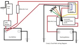
I did some research.... I found out that upgrading the alternator is not an absolute requirement... (the batteries will just charge slower) however, I will still probably do this at some point anyway. The cost of the dual battery setup alone is pretty expensive. I chose to use tried and true Blue Sea components. They were not cheap, but are well made and will hold up over time. They are also relatively waterproof (I like mud puddles). The first shipment from Amazon with the bulk of the items I needed was about $500. After laying everything out I probably spent another $200 or so on other parts. The wiring diagram I have here (see below) I drew up is based off of the diagram that came with the Charging Relay. I drew it up in color and hung it on the wall of the garage during the install so I could easily reference it while I was making all the connections. It was basically my map.
I made my shopping list of major items from another write up by KeithPDX. There were a few more things you will need besides the things he has listed in his post. Here are the items which I purchased mostly through Amazon, Harbor Freight, and Auto Zone.
My Shopping list:
Two DieHard Gold Series Group 34 Batteries (get them from Sears)
Blue Sea Systems ML-ACR 7620 (Automatic Charging Relay)
Blue Sea Systems 285 series surface mount 100amp breaker
Blue Sea Systems Standard blade fuse block (I got 12 circuits)
2 Blue Sea Systems Fuse block with cover
4 Gauge red & Black battery cable (I bought 50' of each-this is overkill)
Two 200 amp ANL fuse
Military Battery terminal and cover set
Ring terminal Connectors (
pack of 10 in 3/8" and various smaller sizes)
Lug Crimping Tool
Dielectric Grease
Marine Grade shrink wrap (Harbor Freight has this as well)
Red & Black Electrical tape (yes, I'm that OCD)
Battery disconnect terminal
Flexible battery terminal covers
Starboard (to make places to mount some of the components)
Small electrical kit containing various ring connectors
Box of 20 gauge wire (assorted colors for wiring up the ACR to the switch)
Techflex 1/2 inch plastic sleeving (red & black)
1/4" and 1/2" Wire loom (mostly used for the ACR to protect those wires and accessory wires)
Single rocker panel switch housing (for the ACR switch)
Low Profile mini fusetap
Assorted standard blade fuses (to go in the fuse box for accessories)
Dual voltmeter (yeah I paid a lot for this, but it fits in the Toyota switch location and pleases my OCD) (solidkit.com/au)
Aux Air pump relocation & battery tray kit from Schrockworks
Various nuts and bolts of varying sizes and lengths to fasten down each component to the starboard (Lowe's, Home Depot, etc)
Tools:
Various sized metric and standard sockets and wrenches
Wire Strippers/crimper
Step stool (if your truck is lifted this is a huge help)
Soldering Iron
Heat gun
3lb hammer
Jigsaw or hacksaw to cut up the starboard
Files or sander to smooth out the starboard edges
Drill with various sized bits
Zip/cable ties
Brute force - to disassemble the dash
Couple of tips... plan to either wire loom or use the Techflex on EVERY SINGLE WIRE. I bought 25 feet each of the Techflex in both colors with plenty left over. Use the dielectric grease on EVERY SINGLE CONNECTION to prevent corrosion (I coated each connector one at a time after the install was complete, and the wiring as I went). The install could probably be done in a VERY long day, but if you are like me and are not a wiring expert, plan to do this over a couple of days. The last three days, I worked on this for about 6 hour periods at a time and I was exhausted. The truck was in pieces for several days in a row. Take your time and double check your work with the diagram.
Before you get to the meat and potatoes:
You will need to relocate the aux air pump in 2013+ models. The kit sold by Schrockworks is well made, with excellent directions. This alone will take a couple of hours to complete. I'm not going over that here because it's already been written up and frankly I could not do a better job than the instructions that are provided with the kit. Just make sure you read all of the details and tips.
The install:
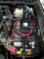
After the air pump was moved I put in the the two new Diehard batteries. You will notice that the terminal connectors to the stock battery are in a different location than on the Die Hard batteries. For the negative cable, I used two pair of pliers and I carefully bent the stock negative connector as straight as I could. For the positive side, I used a Battery Disconnect terminal. It was the longest terminal I could find and it barely reaches the positive side of the terminal, but it works. You will need a longer bolt and nut for this terminal because the connector is fatter than the stock one and you will be attaching another ring connector to the existing stock one. I covered it with a flexible terminal connector and cut out a hole for the release knob.
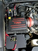
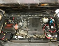
The Schrockworks bracket for the Aux Air Pump (pass side) makes an excellent mounting point for some of the Blue Sea components. You will have to cut the starboard to make several places to mount the ACR, fuses, fuse box, and breaker. I used nuts and bolts to attach them to the truck, and used t-nuts to attach the components to the starboard. Keep in mind that you will need to run wire to all the components, so be cognizant of how much space you are leaving between and around the components when mounting. You can mount them in any location you wish. Because I have my ARB compressor mounted on the driver's side, that sort of eliminated a lot of space I could have used for mounting my battery setup components. I did not want to fill up the bracket, in case I end up with a dual compressor down the road. The ARB dual compressor bracket came from SLEE Offroad and is a very well made bracket. You have to call them to place an order, which sucks, but they are very nice and it was shipped the same day. I chose to make a starboard mount that mirrored my stock fuse box, to mount the ACR and the inline fuse on the driver's side. If you do this just take note of the stock fuse diagram on the inside of the lid and plan accordingly. My hubby also made the mount that is over the top of the Aux battery for the breaker. He designed it so that it stands off above the terminals of the battery, and has small feet to hold up the corners. He used some bolt extenders, washers, and threaded rod with nylock nuts to attach it to the battery j hooks above the battery hold down.
Once you have all of your components mounted you can begin the work of creating all of your connections. I wanted everything color coated which is why I used the Techflex instead of plain black wire loom for everything. I wanted to be able to see where all of my connections were and wanted them obvious in case I need to do any trouble shooting down the road. I did remove the air box just to get it out of the way while I was working, but be mindful of how much space the box needs when running your wires to the aux battery. I used a colored pencil to outline where the box was against the fender side.
When making my terminal connections on the 4 gauge wire, I would cut the plastic off the end of the wire according to how much needed to fit into the terminal connector, put some dielectric grease onto the wire, slide the terminal connector onto the wire, then use my 3lb hammer and the lug crimping tool. It takes a bit of effort to crimp the large wires, so I did this on the concrete floor of the garage. I would double check that the terminal was tight on the wire by yanking on it a few times, then use the marine heat shrink to cover the connection where the connector meets the plastic of the wire. I would attach the terminal to the appropriate component, then measure/roll out the wire to how long the wire needed to be, to match up with the next component. Do this carefully and take into account zip tying it into place. You can bend it into place and make a note of how the next connector needs to be oriented. It won't hurt to have a few extra ring terminals in case you screw up and have to re-do any of the wires. After I measured the length, I would attach the second ring terminal using the same procedure, then cover the wire with Techflex and tape it into place with the electrical tape.
Making all of the connections takes an incredible amount of time. Go slowly and remember to use the marine heat shrink on all the ends and use the Techflex to protect all of the wires.
After I got everything connected I kept the breaker tripped, and did not put in the fuse coming from the start battery. I wanted to get the switch wired up and ensure it worked correctly before "going hot". I did have to make a trip to Jeff's and he was able to:
A. explain/show me how the ACR works, and...
B. make sure I had everything wired up correctly
If you look at the wiring diagram drawing I made, the brown wire running from the ACR to the "Engine/Start" will not be used. Neither will the green wire or the orange wire. You will have to create a "wiring harness" of sorts that runs through the firewall, into the cabin to your switch. So you will need to solder some length onto the ACR wires (which are incredibly short) and marine shrink wrap them. I labeled all of the wires with some tape before running them through the firewall so I wouldn't get confused. This is also a good time to run the one red wire from the aux battery to the switch as well (I forgot to do this, so had to do it later).
The ACR comes with a red Carlin style three position switch. On/Auto/Off. Using the wiring diagram I have here, if you connect everything up, and set the switch to "Auto" the ACR will click on about a minute after the engine is started. After the engine is turned off after about a minute the ACR will click off. You can test this without the engine actually turned on. The ACR makes a very audible thunk/click/clunk sound when it comes on and doesn't sound like any other component under the hood. It is very obvious when it comes on. In hindsight, I probably should have temporarily wired up the switch (before running the wires through the firewall), and tested everything before I ran the wires into the cabin, but I got lucky and everything worked. Another thing... on the back of the switch, make sure you are using
insulated terminal connectors (Jeff yelled at me for not doing that so I have to go back and fix that this week).
I chose to mount the ACR switch in the lower left dash area, next to a single Toyota blank. In the Toyota blank I will have the dual volt meter (still waiting on arrival). I used a Dremel to cut out the hole for the ACR switch housing.
I think this is it. Remember to be cognizant of where you are putting terminal connectors that are connected to the battery. I did accidentally drop a hot end of a connector onto metal twice during the install. It's a reminder to be more careful. For this reason, I recommend connecting to the battery LAST. Make use of the plastic terminal covers and don't rush the project. If you have to stop in the middle of the install and move/drive your truck, please make sure that you remove the ANL fuses and trip the breaker so that nothing is connected until you are completely finished and are ready to test the system and "go hot" so to speak. Please be safe.
If I have left anything out, please let me know and I will cover those areas in more detail. Again... I am not an expert, but this project has taught me a lot about how the system works. I know how it works and why, and to me this is valuable information if I ever get stranded in a situation and have to troubleshoot. :heh:



 aaaaamn Corey! Now that's a post!


