Aftermarket DC-AC Inverter Install

nycrunner

New member
Hey everyone. I'm looking to install an aftermarket DC-AC inverter in my 2008 SR5, and I have my mind set on a permanent-mount inverter that is rated @ 750 - 1,000W (so far, I like the Tripp-Lite products). The tricky part is that I'm looking for an elegant install. In my book, this means trying to make use of as many OEM components as possible.

While my truck was not delivered with the Toyota inverter, the engine compartment fuse/relay box clearly has a slots for a fuse and relay allocated to the inverter. What's more, I purchased an OEM "AC 115V" switch from a scrap-yard, and when I plug it into the existing harness (to the left of the steering column), it illuminates. This is a positive sign!

My guess is that the wiring for the inverter may exist throughout the vehicle. That being said, I've read throughout the forum that the Toyota OEM accessory inverter is only rated to ~100W. This would lead me to believe that the OEM wiring, even if in place, is probably way to light a gauge to support 750 - 1,000W of load. Everyone agree?

Given these likely facts, I think my current mission is to try to hack the existing OEM dash switch so that it can control the on/off of a newly hard-wired inverter in the cabin. I'm hoping some more electrically inclined forum members can help me understand the pinout of this switch, and how to use it to implement a relay-controlled circuit for the inverter. I also need some help selecting the relay itself, as it will need to be able to handle a load of up to 2,000W @ 12V (most of the inverters I’ve come across are rated at momentary load that is 2x the continuous wattage rating). As a part of the executing the relay aspect of the install, I also need some help in understanding literally how I pass a 4-6 AWG direct connection to the inverter through a relay such that the connection itself does not create a significant voltage drop.

Any thoughts would be very much appreciated!
 
Register to hide this ad
You do not need a 4ga wire for your inverter install.

you will not be running that much amperage to require so thick of a wire. a 8 or 10ga wire will be fine.

Buy some quality 8ga from a stereo shop.
Buy a Stinger sr80 high current relay
sr80.jpg

buy a stinger sting-fh3 fuse holder
stinger-stingfh3~2328~1.jpg

i typically buy a stinger spg150 inverter, because it comes with this socket panel
SGP150.png


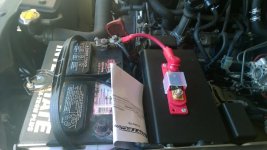
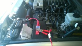
this is what i do to the panel, i take it apart and flush mount it in place like so


thats just a few jobs i did
 
How's the heat on that thing? I know some of the smaller inverters I have used before get very very hot and I would worry about proper cooling, especially if you're talking 2k watt output...
 
Did the OP have any success with this project? Was the inverter able to mount in the factory location in the truck?
 
This is an old thread, but 8 or 10 AWG wire is not quite enough. For a 1000 watt output inverter, assume 80% conversion efficiency, that's about 100A at 12V. This table says you need at least 6 gauge wire. American Wire Gauge table and AWG Electrical Current Load Limits with skin depth frequencies and wire breaking strength
I don't know how efficient inverters actually are, but it could be a lot less than 80%.

Thinner wire will technically work. It won't melt but it will get hot and add excess resistance (voltage drop and inefficiency). With 10 gauge wire and a 10 foot run to the trunk, the inverter will shut off at full load because the 2 volt drop in the wire will make it think the battery voltage dropped below 10V. 17 gauge or thinner wire will melt (the copper will melt) with 100A current according to Wikipedia. Somewhere in between 17 AWG and 6 AWG (closer to 17) it will get hot enough to melt the insulation, short to chassis, and blow a fuse or blow up your electrical system if you didn't add a fuse.

100A is quite a lot for the vehicle's electrical system. The reserve capacity is a stupid unit of measure that says how long the battery will last with a 25A load. With a 1000W load on the inverter, the battery will last less than 1/4 of the reserve capacity. It's less than 1/4 because the capacity decreases with higher load, since there is more loss in the battery. A 24F Duralast Gold has a reserve capacity of 130 minutes, so you will drain it in about a half hour. That's not bad, I guess, but don't drain it all the way or you will damage it. You need a deep cycle battery for that. A dual battery system would help here.

Apparently the stock alternator is rated for 130A. A 100A load will stress it a bit. If it's also trying to charge the battery you just drained, it could be too much for the alternator.

It looks like the factory inverter lives by the driver's side rear wheel well, so there may be space for a bigger one, but you would have to give it air flow for cooling. My little 400W inverter gets hot putting out less than 100W. Non-resistive loads like switching power supplies or motors will make it get hotter and make it run less efficient (drawing more current from 12V). Resistive loads like incandescent lights are easier for inverters. Higher loads increase the efficiency. Non-resistive loads will also draw more power than they usually do if used on a modified sine wave inverter, further reducing the overall efficiency.
 
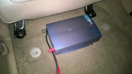
My 600W Inverter Install Under Driver Seat

600W Samlex SSW-600-12A Pure Sine Wave. DonRowe.com: Samlex SSW-600-12A, 600 Watt Pure Sine Wave Power Inverter

I chose this model because it has the smallest dimensions of the many brands/models I looked at it, also I've used this model before with height-adjustable power seats. Dimensions are 9.1" x 6.1" x 2.2". That is small compared to others. Also, it comes with alligator battery clips and terminals for the inverter connection, these come in handy with my install method.

Pure Sine Wave rather than Modified Sine Wave because some devices require PSW and MSW can introduce interference into radios.

Under the driver seat because it requires short DC cable runs. The shorter the DC cable, the better the inverter efficiency.

This is my install, my method, it's quick and sloppier than some may want to do, it can certainly be improved. Install time was 3 hours by myself, truck sitting on the tires.

MATERIALS:

- Inverter
- ANL Fuse Block - DonRowe.com: ANLBF50, 50A ANL Fuse Kit
- Battery cable to fuse block - #2 AWG 6in Red Cable for Inline Fuse Kit
- wire loom - Make your choice of 3/8", 1/2", 1" loom. Some spots the smaller the better. From engine compartment along the frame you may want to use 1" since it allows you room to feed other cables through in the future.
- Dielectric grease
- Connectors of your choice - ring, butt, or the splicer/reducer you'll see I used
- 8' of red and black #8 AWG wire. You don't need 8' of black if you ground the inverter as I did to the seat bolt.
TOOLS:

Your standard tools, nothing special.

INSTALL:

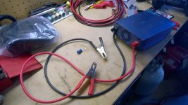
- DESPITE THE BENCH CLUTTER YOU SEE THE VARIOUS MATERIALS.

- REMOVE FOUR BOLTS, MOVE SEAT FORWARD

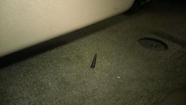
- THERES A GROMMET UNDER THE TRUCK UNDER THE DRIVER SEAT. PIERCE IT, ENLARGE IT AS MUCH AS YOU NEED

- CONNECT THE PROVIDED ALLIGATOR CABLES TO THE INVERTER

- MY METHOD WAS CLIP BOTH ALLIGATOR CLIPS OFF, BUT I REUSED THE RED

- MY METHOD, PUT A RING TERMINAL ON THE BLACK CABLE, SCRAPE THE SEAT BRACKET TO BODY CONNECTION TO BARE METAL, DIELECTRIC IT

- RUN THE RED WIRE DOWN THROUGH THE GROMMET

- UNDER THE HOOD, CONNECT THE BATTERY TO FUSE BLOCK CABLE

- I RIVETED THE FUSE BLOCK IN THAT LOCATION BECAUSE THE DRILL HOLES DIDN'T OBLITERATE THE WRITING ON THE UNDERSIDE OF THE FUSE COVER

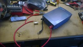
- MY METHOD WAS USE THE SPLICER BLOCK TO REUSE THE ALLIGATOR CLIP TO MAKE THE POWER CONNECTION INSTEAD OF GETTING FANCY WITH A SWITCH. THE INVERTER ALREADY HAS ONE, I DON'T NEED ANOTHER

- THEN YOU RUN THE RED CABLE ALONG THE FRAME WITH WIRE LOOM, ZIPTIE EVERYTHING APPROPRIATELY

- THEN (WHICH I DIDN'T PICTURE) YOU MUST USE THE SECOND SPLICER BLOCK TO COUPLE THE INVERTER RED DC CABLE TO THE BATTERY RED DC CABLE. THAT CONNECTION IS MADE UNDERNEATH THE TRUCK

- THEN YOU PUT THE SEAT BACK IN PLACE, THE BLACK DC RING TERMINAL GOES BETWEEN THE SEAT BRACKET AND THE BODY.

- MY METHOD IS PUT THE RED ALLIGATOR CLIP IN A BAG UNDER THE HOOD, HOOK IT UP AS NECESSARY

- THE INVERTER ON/OFF SWITCH IS ACCESSIBLE EVEN WITH THE REAR SEAT FOLDED DOWN

I apologize particularly for the crappy ring terminal connection, but I had to solder it and it came out ugly.

Oh well, heaping helpings of dielectric, electrical tape and wire loom cure a lot of electrical ills.

It works. Plug your AC cord into the outlet, clean up the install as you please, run AC out a window to wherever you please, run a AC cord to an interior 3-prong.
 

Attachments

  • 4runner inverter.3.jpg
    4runner inverter.3.jpg
    135.6 KB · Views: 2,252
  • 4runner inverter.5.jpg
    4runner inverter.5.jpg
    136.5 KB · Views: 2,482
  • 4runner inverter.7.jpg
    4runner inverter.7.jpg
    130.8 KB · Views: 2,510
  • 4runner inverter.6.jpg
    4runner inverter.6.jpg
    137.2 KB · Views: 2,701
  • 4runner inverter.4.jpg
    4runner inverter.4.jpg
    130.7 KB · Views: 2,554
  • 4runner inverter.8.jpg
    4runner inverter.8.jpg
    130 KB · Views: 2,876
  • 4runner inverter.11.jpg
    4runner inverter.11.jpg
    150.6 KB · Views: 2,971

Members online

Forum statistics

Threads
278,316
Messages
3,554,105
Members
248,016
Latest member
Advally Service

Trending content

Back
Top