BFAD's SuperFlow MV-50 Air Compressor Build

BigFishAllDay

New member
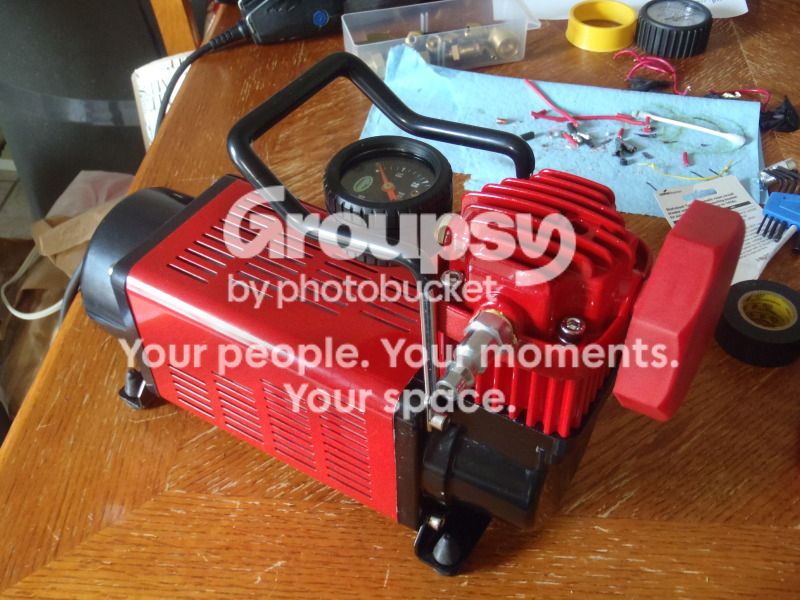
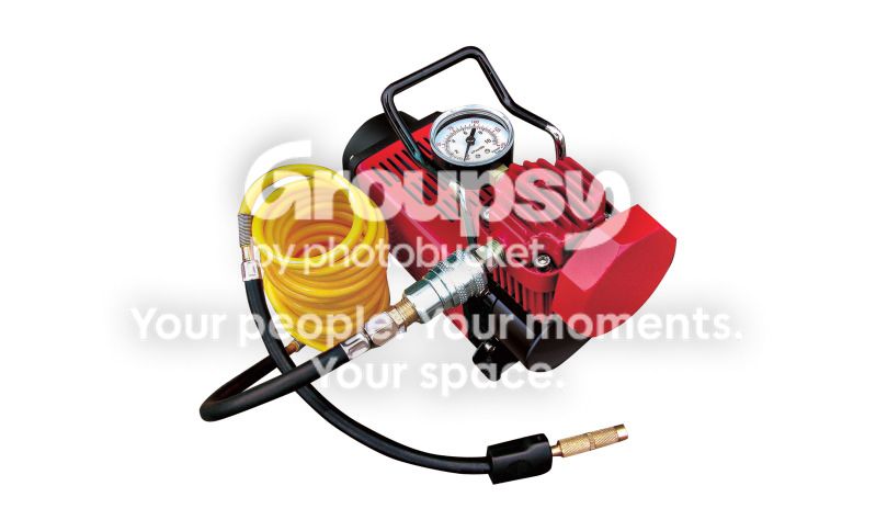
This thread will cover the teardown and re-build of my recently purchased Q Industries MV50 SuperFlow Air Compressor.

Before you ask, "Why such a detailed write-up on a cheap little compressor?"

Well, because we all like cheap solutions that work well, and an air compressor is a valuable tool to have while 4-wheeling. With a few tweaks, the MV-50 is a cheap compressor that works very well.
2_zps0a1d5467.jpg~original


I'm not the first guy to re-work one of these compressors, and I'm sure I won't be the last, but I did do a few things differently than others have. Also, since I couldn't find any detailed threads on this compressor on T4R.org, I figured I'd go ahead and make one.

Having two 4Runners, I like having a compressor that I can move back and forth between vehicles rather than a hardmount. I also wanted something simple with decent performance. The MV-50 regularly sells on Amazon for anywhere from $50-60, so I read the reviews and did some research.

Most of the negative reviews on this compressor center around the same problems:

1. The air fittings are a non-standard size, as are the threads on the fittings.
2. The power cord overheats with extended use.
3. When re-starting against a significant head of pressure, the compressor will often blow it's fuse.
4. The relay sometimes fails/melts.
5. The air hose can melt with extended use and/or crack in cold weather.
6. The pressure guage is inaccurate.

The negative reviews make up about 27% of the 186 product reviews on Amazon, with the remaining 73% being 4 Stars or better, so my impression is that most of these compressors work just fine out of the box. I think the negative reviews are due, in the following order, to:

1. The unit being run at it limits by demanding owners (mostly those who are using it for trail duty)
2. User error
3. Manufacturing defects & quality control

Ultimately, when you're buying a $50, "Made In China", air compressor you have to expect that there is at least a small possibility it could have some issues. BUT, I like to tinker with things and I figured it would be fun to tear one down, learn how an air compressor works, and address any issues in the process.

Link to the Amazon page for the MV-50 > Q Industries MV50 SuperFlow High-Volume 12-Volt Air Compressor

...
......
..........
............................

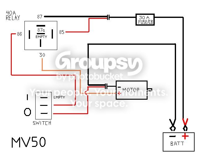
To start, I made a wiring diagram of the compressor's power & ground circuits for future reference, and to guide me in re-wiring it with better components.
MV50_zpsea60b1cf.jpg~original


Before disassembling the compressor, I did a quick performance test:

-Ambient temp: 45 degrees F
-Compressor connected to vehicle battery
-Engine idling @ ~700 RPM
-Tire: 285/75r16 Goodyear Duratrac, E-Load Range
-Starting tire pressure:15 PSI
-Compressor run time: 3 minutes
-Ending tire pressure: 27 PSI

In 3 minutes, the stock MV-50 was able to inflate the tire 12 PSI. I used a pencil type air pressure guage which tends to read a little low, but for consistency I will use the same guage on the "after" test.

NOTE: BE ADVISED, IF YOU CHOOSE TO DISASSEMBLE AND MODIFY YOUR MV-50 COMPRESSOR, YOU WILL VOID THE WARRANTY!

Using a 4mm hex key, I started by removing the two bolts that secure the carrying handle. Then I moved to the end where the power cord connects to the unit and removed the four bolts securing the endcap that covers the wiring & relay.

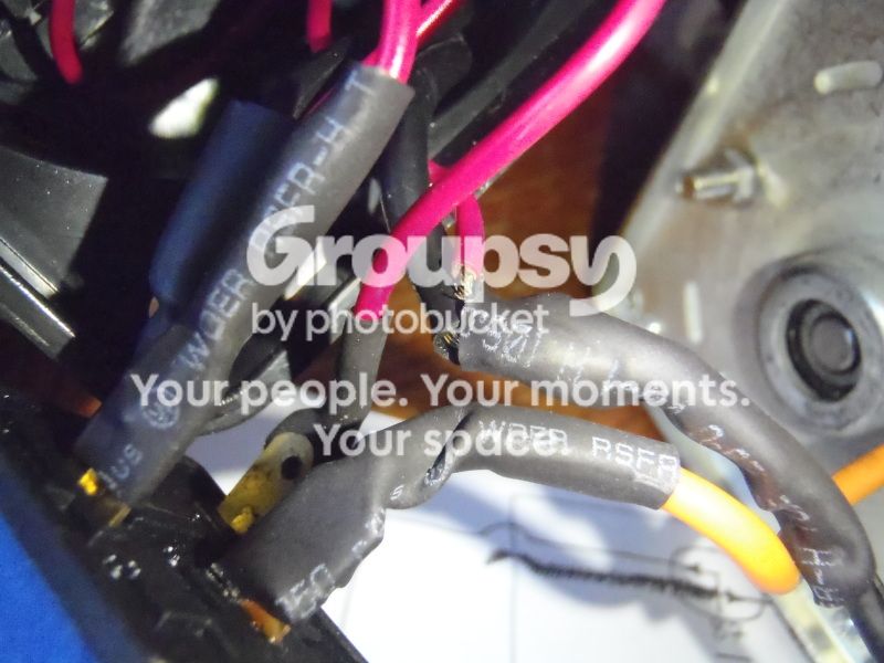
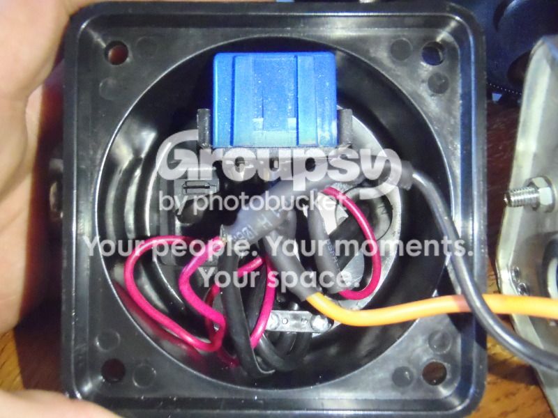
First look at the unit's wiring:
PC281970_zps0937428e.jpg~original


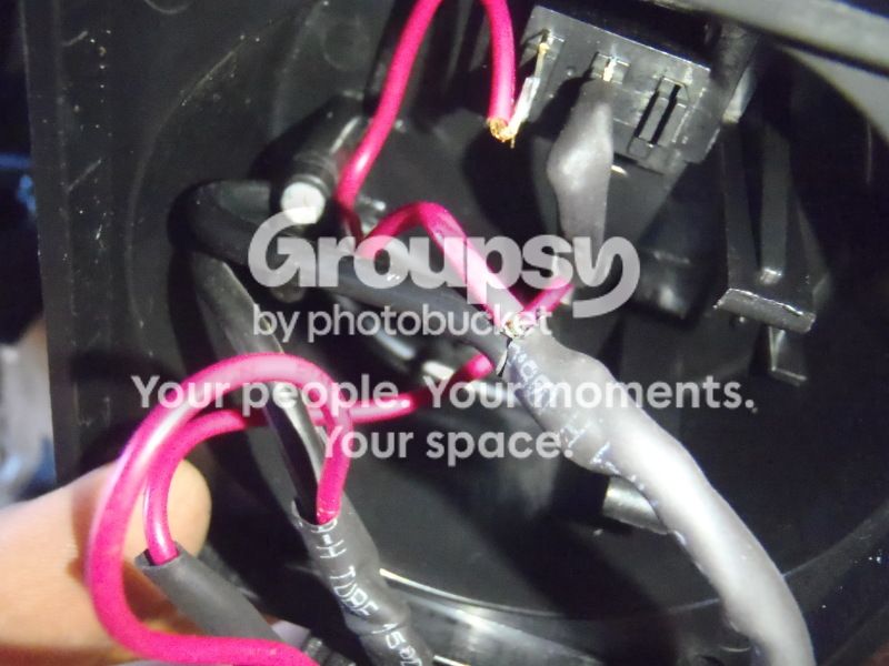
I noticed that the manufacturer didn't do the best job of insulating the wiring & connections:
PC281975_zps7f7be582.jpg~original


PC281977_zps6800b725.jpg~original


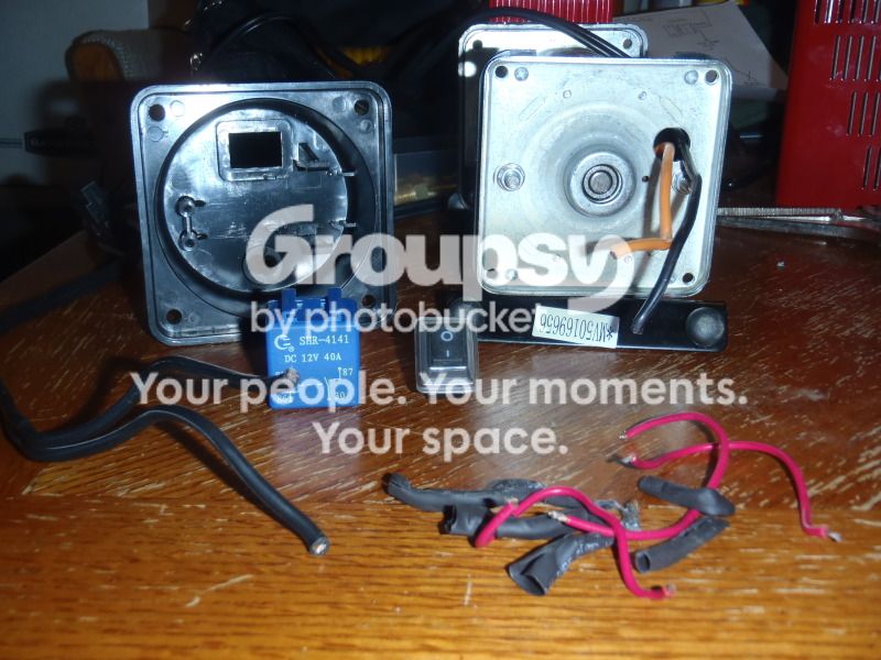
Next I cut the relay out of the harness so I could check it out (all the connections inside the unit were soldered, not quick connects). I'm not surprised that people encounter problems w/the relays. It appears to be just a cheap "no-name" 40A SPDT relay.
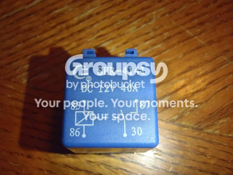
PC281978_zps230c1540.jpg~original


Next up I removed the switch and it's associated wiring...
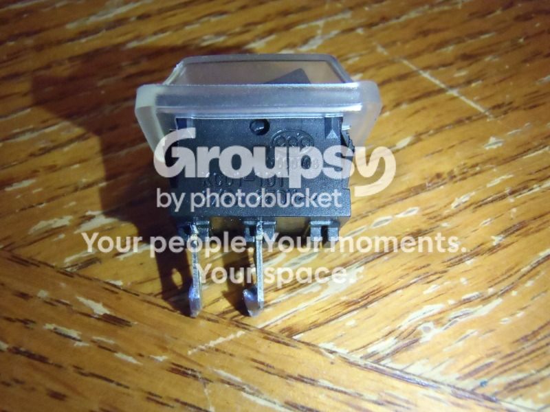
PC281980_zps505799b7.jpg~original


Electrical side, disassembled...

PC281984_zps0456b840.jpg~original


Now it was time to work on the mechanical side of the compressor and tear down the cylinder head, cylinder, heat sink, air fittings, and pressure guage.

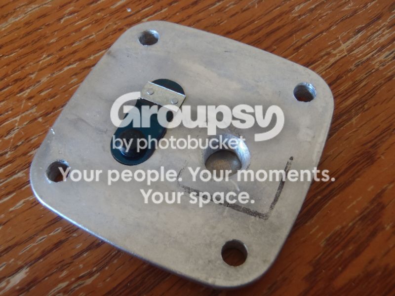
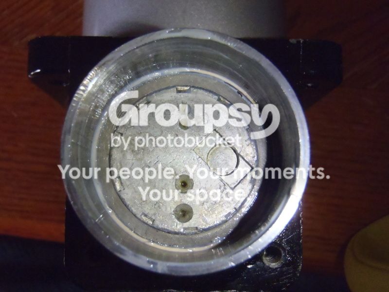
A close up shot of the cylinder head, shown with the air fitting, inlet filter, and pressure guage removed:

(The quick connect air fitting can be removed using a 14mm wrench or deep socket, and I used vice grips to remove the pressure gauge.)
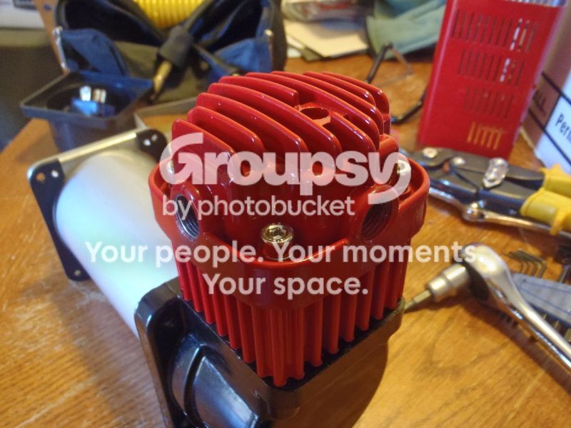
PC281986_zps034b13bc.jpg~original


Using the 4mm hex key, simply remove the 4 bolts on top and the intake/exhaust manifold comes right off. The 4 bolts on my compressor were very loose and two of them just spun out with no resistance using the hex key. Considering that the torque on these bolts seals the cylinder head (which is claimed to hold 100+ PSI), I'm surprised there wasn't more torque on them.
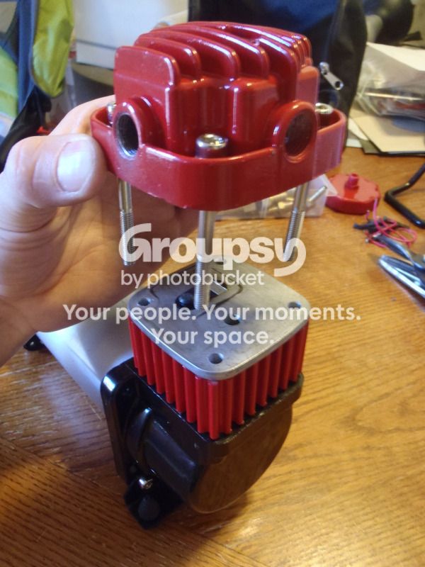
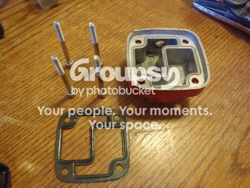
PC281988_zpsc5b25df9.jpg~original


PC281989_zps6f126bb8.jpg~original


The following shots are just some close up "before" shots I took of the cylinder head, heatsink, and piston:

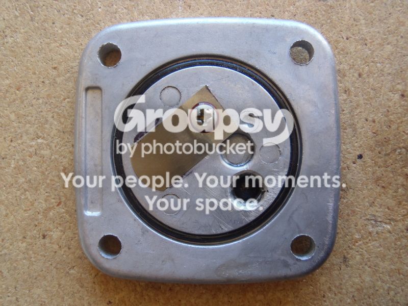
Top of Cylinder Head, exhaust reed valve (left), and intake port (right):
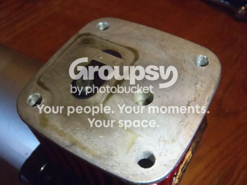
PC281990_zps38199e4e.jpg~original


Bottom of Cylinder Head, intake reed valve (top), and exhaust port (bottom). Also, note O-ring seal that sits in the groove for the piston cylinder:
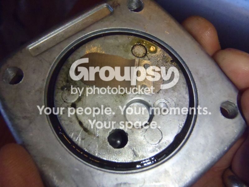
PC281992_zps6102ef01.jpg~original


A close up of the Piston, Cylinder, and Heat Sink. Notice that the heat sink does not fully contact the piston cylinder. There are only 4 ribs of material that actually make contact between the two parts. This is a considerable design flaw. If the heatsink made full contact with the cylinder it would function much more efficiently.
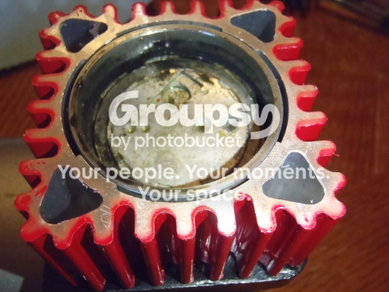
PC281993_zps3ad8f872.jpg~original


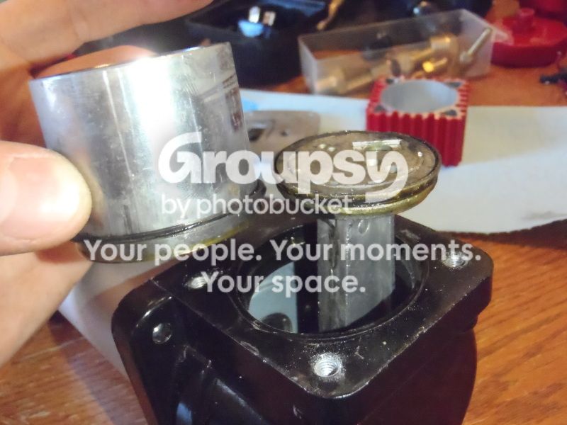
Cylinder removed from piston, note O-ring seal around bottom of cylinder, forming a seal between bottom of heat sink, outside surface of cylinder, and crankcase.
PC281996_zps82d23c42.jpg~original


Cylinder, showing abnormal wear pattern from deformed piston ring (see comments on piston photo below)

PC281997_zps36986bbc.jpg~original


Cylinder, showing deposits of hard resin like substance.

PC281998_zps885bd479.jpg~original


Piston Top, note hard plastic piston ring which acts as a sealing surface between the piston and the cylinder wall. The piston ring on my compressor had a deformation (visible @ top, left of center on piston) where the ring had folded over on itself. Despite the deformation it still appeared to be forming a good seal, judging by the wear marks on the cylinder wall (see pics above)

PC282001_zps2f42f465.jpg~original


Piston, Side... this shot shows a little better angle on the hard plastic piston ring, and also illustrates the rough cast surface of the piston itself. All the small indents, gouges, and rough surfaces make it look like the piston was put in a polishing drum with a bunch of rocks.

PC282002_zpsad92c9c4.jpg~original


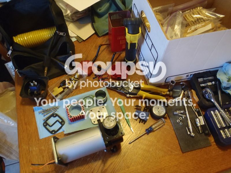
Now we're getting somewhere, all torn down. Christmas Cookies make a handy snack while you're tuning up an air compressor!

PC282000_zpsa578229f.jpg~original
 
Register to hide this ad
Porting the cylinder head, new gauge & wiring.....

The first modification I decided to do was open up the intake and exhaust ports on the cylinder head. While it won't increase the max CFM of the compressor, this should improve the efficiency of the compressor overall, while helping it to run cooler.

Once again, for reference, the intake port in stock form:

PC281990_zps38199e4e.jpg~original


The cylinder head is aluminum and the material is pretty soft. To open up the ports I used a #194 "High Speed Cutter" Dremel Bit. (Link > Dremel 194 Bit)

After porting:

PC292008_zps82f7be05.jpg~original


Exhaust port, stock:

PC281992_zps6102ef01.jpg~original


And ported:

PC292007_zpse0cf85b8.jpg~original


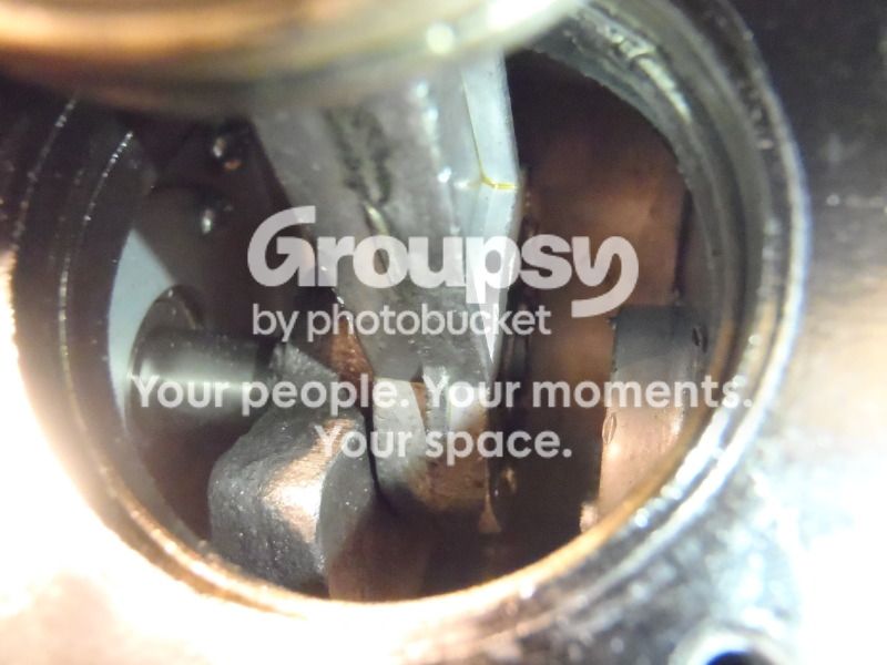
While I had the compressor torn apart, I took a peek down inside the crank case and considered whether or not it would be worth it to try and perfect the alignment of the piston with the cylinder... I decided it wouldn't be worth the time for minimal gains, but took a few pictures anyway.

PC282003_zps9b7f7fe7.jpg~original


The main "rod bearing" where the piston connects to the crankshaft:

PC282004_zpsc40de8f9.jpg~original


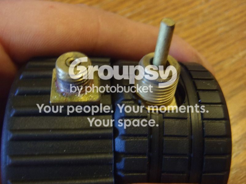
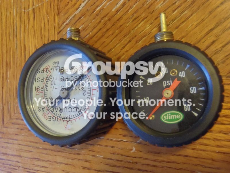
Next I decided to get rid of the crappy pressure guage that was installed on the compressor. The guage read about 15 PSI high and was completely useless for determining tire pressure. I followed the suggestion I found in other write ups and purchased a "Slime" brand tire gauge which can be found at many auto parts stores.

The problem with the guage was that ALL of the other write-ups I had read told me that the new "Slime" gauge would thread right into the port on the cylinder head. Unfortunately that was not true. The threads on the stock guage were quite a bit smaller than the the threads on the new one.

The new guage had 1/8" NPT threads, and I had a tap in the garage, so I just drilled the hole and tapped some new threads. Finally I added some teflon sealing tape and installed the new gauge.

PC292009_zps960cee3f.jpg~original


PC292010_zpsdff2c75d.jpg~original


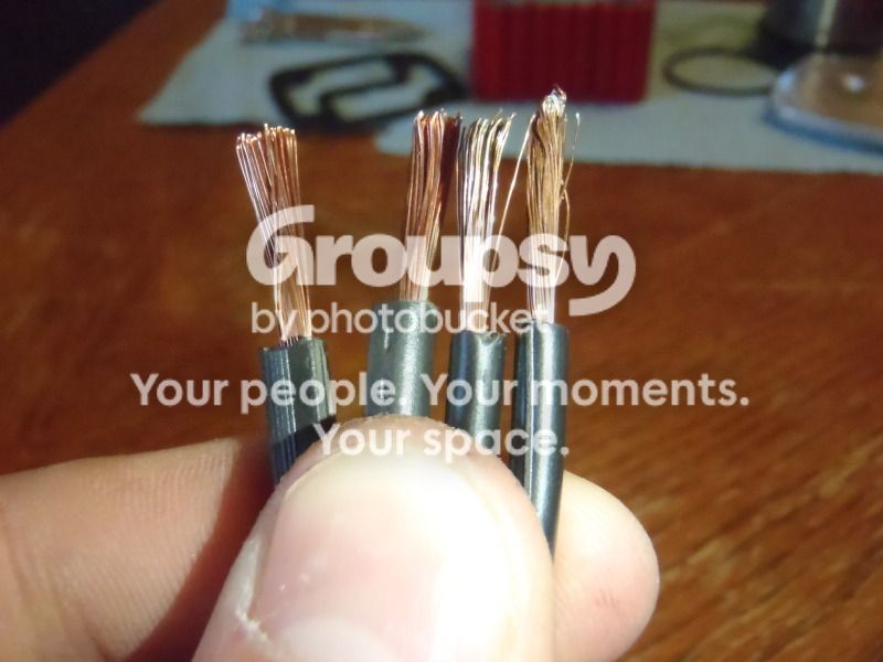
Up next was the power cord & fuse holder. The stock power cord is made of 14 AWG wire with an inline ATO blade-type fuse holder containing a 30 amp fuse.

I replaced the 9 foot stock power cord with 10 feet of 12 AWG "Underground Low Voltage Landscape Lighting Wire". The new wire has more strands, steps up an AWG size, and has thicker PVC insulation. This should allow the motor to more easily draw the current it needs from the battery, help the wire run cooler, and the thicker insulation will help if/when the wire heats up.

New on left, old on right:

PC292011_zps6a0f8266.jpg~original


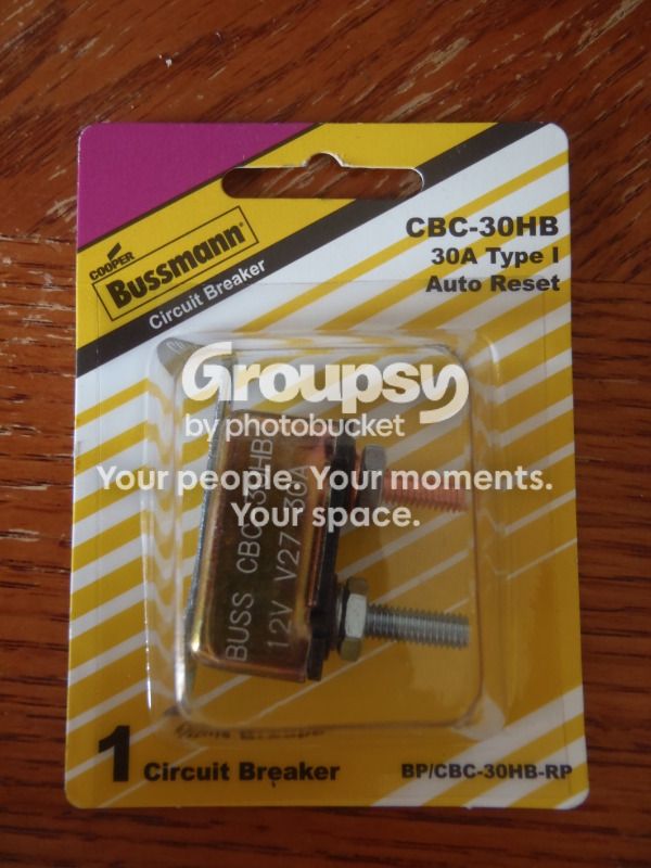
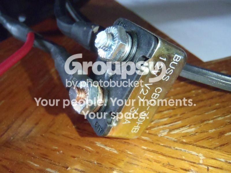
Since the new cord eliminated the fuse holder, I decided to go with something a bit simpler and chose a 30 AMP Auto Re-setting circuit breaker for $4. This will eliminate the need to carry extra fuses, since the circuit breaker has the ability to re-set itself multiple times. Also I can house the circuit breaker inside the end cap with the other wiring.

PC302014_zps56bbc63c.jpg~original


I used the Dremel to shorten up the studs on the breaker, and some aviation snips to cut off the mounting brackets at either end.

PC302015_zps6c3cc1a2.jpg~original


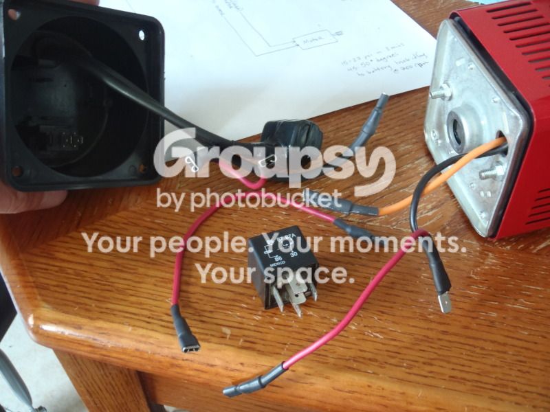
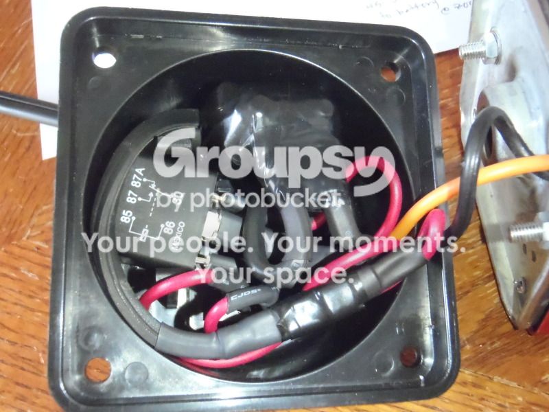
Last but not least, I got rid of the stock "el cheapo" relay and put in a DEI 30/40A Starter Kill relay I had leftover from the alarm install. I also replaced all the stock 16 guage wiring with 14 gauge and re-built the harness with quick disconnects and more precise application of heat shrink tubing. The circuit breaker was also fully wrapped in several layers of 3M electrical tape to prevent shorting.

PC302016_zpsbbc2c42d.jpg~original


The new wiring, relay, and circuit breaker all fit nicely inside the endcap. Here's some before/after shots of the wiring:

Before:

PC281970_zps0937428e.jpg~original


After:

PC302017_zps22446fca.jpg~original


I cleaned up all the mechanical components and gave them a coating of engine assembly lube...

PC302012_zps3154c842.jpg~original


And it was done...

PC302018_zps37e55bde.jpg~original


Remember those issues I mentioned earlier?

1. The air fittings are a non-standard size, as are the threads on the fittings. For now I'm going to stick w/the stock fittings, and if/when the air hose fails I'll drill & tap for 1/4" NPT and install an upgraded hose/air chuck.
2. The power cord overheats with extended use. UPGRADED! Check.
3. When re-starting against a significant head of pressure, the compressor will often blow it's fuse. The instructions call for the user to start the compressor first, THEN attach it to the valve stem. If you try to start it while it's attached to a valve stem with 60 PSI on it, the motor will stall, draw a ton of amps, and pop your fuse. Read the manual.
4. The relay sometimes fails/melts. UPGRADED! Check.
5. The air hose can melt with extended use and/or crack in cold weather. See #1
6. The pressure guage is inaccurate. UPGRADED! Check.

With the tune up I performed, this little compressor should be good to go. :D

As always, I'm going to include a references section. These are the links that I found useful in researching the compressor and associated mods:

Manufacturer's Website

SuperFlow:: Tools Not Toys!

General Info

Harbor Freight vs Costco Portable 12v Air Compressor - In Depth Review w/ Pictures - JeepForum.com

Mod threads

My Costco Q-Maxx / MV50 Compressor build - JeepForum.com

Hot Rodded Compressor - Expedition Portal

Porting threads

Cheap air compressor porting - TTORA Forum

Porting the Superflow MV50 Compressor - 4x4Wire.com

TrailShot Galleries - Superflow MV50 - 4x4Wire.com

General Writeups & Info

air compressor test

Superflow MV-50

Awesome Air Compressor Comparison Test

On Board Air w/Tank using MV50

4x4Wire - Portable Onboard Air Installation
 
Last edited:
After I put everything back together I decided to do an "after" test. I deflated my tire to 15 PSI, hooked up the compressor and let it go to town.

At 2:23 into the test, there was a drastic change in the tone of the noise the compressor was making. It sounded like it slowed down significantly as well. First thought: "Crap! There goes $50!"

I figured I had screwed something up and damaged the compressor, so I just let it finish it's test and turned it off @ 3 minutes. When I disconnected it, I ended up with the EXACT same results... 15 PSI to 27 PSI in 3 minutes. A little disheartening, so I said Fk-it and just left it running another 5 minutes...

When I turned it off I was still at 27 PSI. Yup, something is wrong.

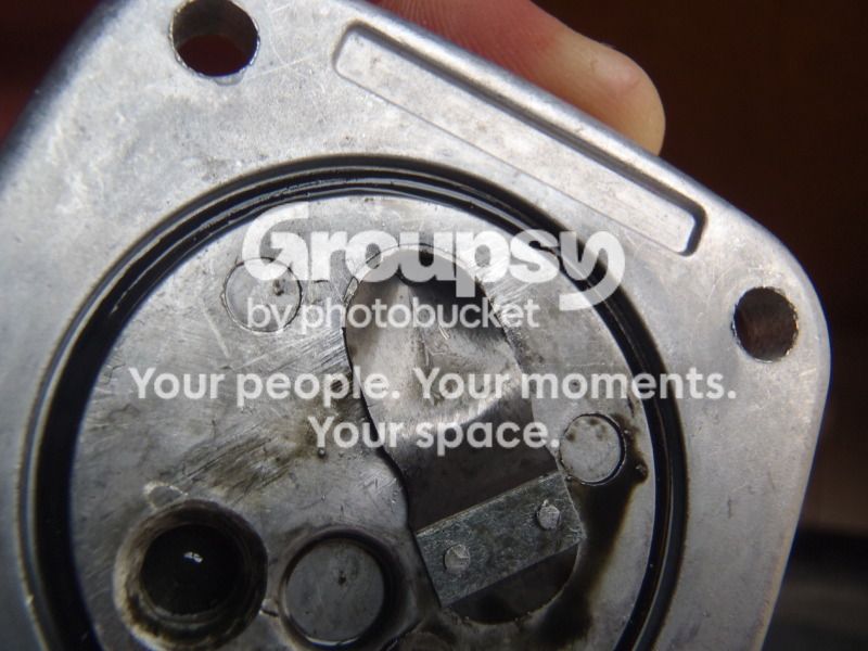
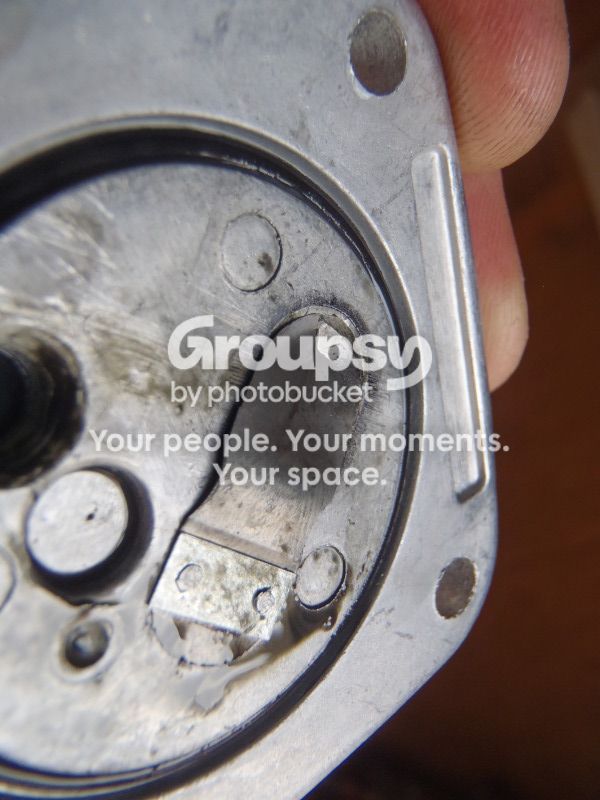
I figured the damaged piston ring may have failed completely, but when I took it back apart I was surprised to find:

PC302019_zps7c4e7375.jpg~original


PC302020_zps9faa9f6f.jpg~original


PC302021_zps7b5d0eee.jpg~original


WHOA! I guess I got a little too happy with the porting and I didn't leave enough material under the edges of the intake reed valve. When the compressor started to build pressure it pushed the reed valve up into the intake port on the exhaust stroke, cracking the reed valve and jamming it inside the intake port. This blocked the compressor from drawing in more air, which is why I heard it slowing down. It essentially had a clogged intake.

Good news, and bad news...

The good news is that in 2:23 (time to failure) the compressor got the tire to the same pressure that it took 3:00 to reach before the mods.

Also, it's repairable.

Bad news, I get to grind the rivets off the intake reed valve, cut a new reed valve, drill & tap a screw hole to secure it, and try again.
 
Last edited:
Just an update:

In your relay diagram, no 30 goes to the +12 battery and 87 and 87a are for accessories output.

I have a $10 harbor freight compressor and takes 20 minutes to pump 1 tire.
 
YES. This is like BFAD's un-directed Christmas present, to me..... haha sub'd fo sho!

Yeah right! You might be looking at the MV-50 as a backup, be we all know you're a high roller and you've got your eyes on the VIAIR Constant Duty system. (Late) Merry Christmas to you, man!

HOLY COOKIE MONSTER!

NOM! NOM! NOM! COOKIES! ME WANT COOKIES!

Just an update:

In your relay diagram, no 30 goes to the +12 battery and 87 and 87a are for accessories output.

I have a $10 harbor freight compressor and takes 20 minutes to pump 1 tire.

Just an update: it works either way. In this case I used a SPDT relay to do the job of a SPST relay (which was used in the stock setup), but there is no need to switch the flow of current between 87 and 87a, so they put the 12V in @ terminal 87 (normally open) and the 12V out @ terminal 30 (common). When the coil is energized it opens terminal 87a (normally closed) and closes the circuit between 87 and 30, flowing power to the motor.

I drew the wiring diagram based on how the wiring was setup from the factory when I disassembled the compressor, because that is what people are going to see if/when they choose to mod their own MV-50's. I re-assembled it the exact same way because it will work just fine, and exactly as it was intended to.

A case of Potato, PoTATo.
 
Last edited:
Nice write-up! I had one of those a couple years ago for a back up when I ran out of Co2. The wiring shorted out the second time I used it and I had to rewire it like you did (I also tore mine all apart for the hell of it). It's an okay compressor if you have smaller tires and your not airing down super low, but it's real slow if you have larger tires. It would take almost 20 minutes to air up one of my 35x12.50x15 from 8 psi to 30 psi.

Also, you will eventually want to get rid of the air hose and chuck that comes with the compressor. It drove me crazy and the chuck never seemed to work right, I would install a standard coupler and air hose (like you talked about) with a nice clip on air chuck.
 
Thanks BFAD

The MV50's were on sale for around $40 just before xmas so this write up is perfect timing for me. Looking forward to a job I can do indoors - it's been cold in CO! Thanks for taking the time to document and share.
 
i can confirm the cold in colorado...
looks like it's time to open up my compressor and upgrade a few things
better to do it now before trail season kicks into high gear
thanks for the write up!
 
Nice write-up! I had one of those a couple years ago for a back up when I ran out of Co2. The wiring shorted out the second time I used it and I had to rewire it like you did (I also tore mine all apart for the hell of it). It's an okay compressor if you have smaller tires and your not airing down super low, but it's real slow if you have larger tires. It would take almost 20 minutes to air up one of my 35x12.50x15 from 8 psi to 30 psi.

Also, you will eventually want to get rid of the air hose and chuck that comes with the compressor. It drove me crazy and the chuck never seemed to work right, I would install a standard coupler and air hose (like you talked about) with a nice clip on air chuck.

Thanks, Jeremiah. I'm working on that last part, but you wouldn't believe how hard it is to track down a 1/4 NPT tap around here. Lowes and Home Depot were a bust... I went to Ace/Tru Value but they were closed. Next time I get some time off I'll go to the shop where I got the 1/8" NPT tap and be done with it.

The MV50's were on sale for around $40 just before xmas so this write up is perfect timing for me. Looking forward to a job I can do indoors - it's been cold in CO! Thanks for taking the time to document and share.

No problem man. I actually did this write-up to answer your request. I saw your comment in my build thread and until then I had it on the back burner. My Wife went out of town for the weekend w/the baby and I was on graveyard shifts, so I had a couple hours each day before work to knock it out.

Glad you found it helpful, and that I could send a favor back your way.

i can confirm the cold in colorado...
looks like it's time to open up my compressor and upgrade a few things
better to do it now before trail season kicks into high gear
thanks for the write up!

You're welcome. It's a fun project man, good luck.
 
So I've been meaning to follow up on the intake reed valve fix. I replaced the reed valve and ran the "3-minutes from 15 PSI" test again, using the same tire guage to check before/after pressures.

After modifiying the compressor, the test results were:

-Ambient temp: 40 degrees F
-Compressor connected to spare deep cycle battery, out of vehicle
-Tire: 285/75r16 Goodyear Duratrac, E-Load Range
-Starting tire pressure:15 PSI
-Compressor run time: 3 minutes
-Ending tire pressure: 30 PSI

So, 15 > 27 before (+12 PSI), and 15 > 30 after (+15 PSI)... That's a 3 PSI increase increase over the 3 minute period, which my simple math tells me is a 25% increase in air up speed from 15 PSI. Not too shabby for $10 and a couple hours. :whoo:

Last, I took a few pictures of the install of the new intake reed valve...

I had a set of feeler gauges that I haven't used since I rebuilt my Supra engine, so I decided to cut the end off one of them and use it for my new reed valve.

The factory installed reed valve was 0.004" thick based on my comparisons to the feeler gauges. I went with a 0.005" thick replacement reed. I wanted a little extra thickness so the reed would hold up to the pressure on the exhaust stroke, while retaining enough flexibility for the reed to easily open on the intake stroke.

I used a small machine screw to make a tap by cutting notches into the threads on opposite sides with a narrow cutoff wheel. After I drilled/tapped the hole, I cut the same screw down to a shorter length and used it to secure the new reed. I applied Red Loc-Tite to keep it in place. Also, I put a slight bend in the new reed with the inside of the bend facing down. This makes the reed like a spring and applies some pressure to help it seal quickly and completely on the exhaust stroke.

The new reed is also thicker, leaving more material sitting around the lip of the intake port, which along w/the extra thickness, should prevent the reed from getting pushed into the intake port. Note the size of the old reed (visible to the right) vs. the new reed.

PC312024_zps910e0329.jpg~original


PC312022_zps2867894c.jpg~original


Side view of the screw head. You have to use a low profile screw here, otherwise you may have interference issues w/the piston on the exhaust stroke.

PC312023_zps6d5f72a3.jpg~original


The piston on my compressor actually had a small indentation cast into it at the very spot where the new screw was installed (visible top center in pic below), as if they intended for the reed to be secured with a small machine screw in the first place.

PC282001_zps2f42f465.jpg~original


...

.......

............

In summary, with:

- Enlarged intake & exhaust ports
- Upgraded intake reed valve
- Upgraded relay
- Upgraded power wire & circuit breaker
- New pressure guage

I was able to net a measured 25% performance increase in the pressure range where the compressor will be used most often. I also believe that I've greatly increased the durability and reliability of the compressor w/these mods.

Tonight I aired up all 4 tires consecutively from 20-37 PSI, running the compressor off a spare deep cycle battery, and it performed flawlessly. It was sufficiently speedy for my needs and I look forward to getting more use out of it on the trail.
:yo:
 
Huh, I never thought of upgrading mine. I figured I'd just get a new one when it crapped out. My only gripe so far has been the useless pressure gauge... I just carry another gauge in the compressor's tote bag :/
 
Another job well done man. How you are so patient in so many minute and time consuming details is beyond my normal normal ability. You should submit your findings, analysis and final result to Superflow...coz wow you've literally man handled their design team of engineers..lol

Good work!
 
Another job well done man. How you are so patient in so many minute and time consuming details is beyond my normal normal ability. You should submit your findings, analysis and final result to Superflow...coz wow you've literally man handled their design team of engineers..lol

Good work!

I highly doubt they have an "engineer." More like they reverse engineered/copied an existing design and made it cheaper. All 12v compressors are essential the same, it is the quality of the components that determines if it is a POS or not. They probably just bought the design off of some firm in China, slapped a "Superflow" label on it, and called it a day!
 
No problem man. I actually did this write-up to answer your request. I saw your comment in my build thread and until then I had it on the back burner.

Thanks buddy - I appreciate it!

1. The air fittings are a non-standard size, as are the threads on the fittings. For now I'm going to stick w/the stock fittings, and if/when the air hose fails I'll drill & tap for 1/4" NPT and install an upgraded hose/air chuck.

The air fitting on mine looks like a standard 1/4" fitting. Any hose should connect - am I missing something?
 
i spent time this weekend working on mine and have some observations
i've used mine maybe 6 times before taking a closer look at it
the first thing i noticed was that the fuse, fuse holder and some of the wire insulation had melted.
i had no idea it got that hot.
next i noticed that all the wiring, soldering etc was horrible
wires were corroded, solder contacts were barely attached or only half the wire was touching
no wonder these things burn out or break quickly

i had the parts on hand to fix the wiring issues so i'll check it after each use for problems

i also had the parts to replace the pressure gauge and hose fitting.
the holes drilled on the head are metric and require drilling and tapping for our 1/4" npt parts to fit.
the actual hose connection is our normal 1/4" but the threads are not
this is where i messed up. i cracked the head while tapping one of the holes.
i have a ton of pipe thread dope in there so i'll see if it holds
otherwise i'll order another one and take my chances again.

so even if you guys don't tackle the drilling and tapping, fixing the wiring issues will definitely help

and i'm an idiot, i have no pics :ybrick:
 
You should submit your findings, analysis and final result to Superflow...coz wow you've literally man handled their design team of engineers..lol

More likely they started with something similar to his version and are now selling it for a profit at 50 bucks!

Looks like it was a fun project!
 
I just realized I never answered these replies to the thread...

That is pretty sweet, nice job!

Thanks man!

Huh, I never thought of upgrading mine. I figured I'd just get a new one when it crapped out. My only gripe so far has been the useless pressure gauge... I just carry another gauge in the compressor's tote bag :/

I wouldn't say the compressor NEEDS to be modified. It works pretty good out of the box. I keep a separate pressure gauge, too. I guess I just like to tinker with stuff and take things apart.

Another job well done man. How you are so patient in so many minute and time consuming details is beyond my normal normal ability. You should submit your findings, analysis and final result to Superflow...coz wow you've literally man handled their design team of engineers..lol

Good work!

Thanks, dude. Alot of this stuff gets done when I have time on my hands... I can't stand watching TV, so I get busy. Plus, now that I'm at home more with my Wife & Baby, I have all that time I used to spend fishing to work on the rigs/toys. It's bittersweet.

I highly doubt they have an "engineer." More like they reverse engineered/copied an existing design and made it cheaper. All 12v compressors are essential the same, it is the quality of the components that determines if it is a POS or not. They probably just bought the design off of some firm in China, slapped a "Superflow" label on it, and called it a day!

I'd bet you're exactly right. These compressors are very similar in design to one of VIAIR's models. They share alot of design cues with one of Harbor Freight's compressors, and they are marketed under multiple brand names. I'm not sure where they got the design, but I'm sure it wasn't original.

Thanks buddy - I appreciate it!

The air fitting on mine looks like a standard 1/4" fitting. Any hose should connect - am I missing something?

I'll have to double check, but I thought the air fittings on these were just a little different, preventing them from connecting to standart 1/4" female air couplings. Maybe I read it during my research and it just stuck.

i spent time this weekend working on mine and have some observations
i've used mine maybe 6 times before taking a closer look at it
the first thing i noticed was that the fuse, fuse holder and some of the wire insulation had melted.
i had no idea it got that hot.
next i noticed that all the wiring, soldering etc was horrible
wires were corroded, solder contacts were barely attached or only half the wire was touching
no wonder these things burn out or break quickly

i had the parts on hand to fix the wiring issues so i'll check it after each use for problems

i also had the parts to replace the pressure gauge and hose fitting.
the holes drilled on the head are metric and require drilling and tapping for our 1/4" npt parts to fit.
the actual hose connection is our normal 1/4" but the threads are not
this is where i messed up. i cracked the head while tapping one of the holes.
i have a ton of pipe thread dope in there so i'll see if it holds
otherwise i'll order another one and take my chances again.

so even if you guys don't tackle the drilling and tapping, fixing the wiring issues will definitely help

and i'm an idiot, i have no pics :ybrick:

Interesting observations, especially regarding the melted insulation and poor wiring work. Those seem to be the most common complaints with these things. Thanks for confirming what SoManyRoads posted above regarding the hose connection being a normal 1/4" size. Sorry to hear you cracked the head on yours, I was worried about that happening, which is why I held off on replacing that fitting for the time being.

More likely they started with something similar to his version and are now selling it for a profit at 50 bucks!

Looks like it was a fun project!

Exactly.. They just found some places to cut corners on cost (wiring, relay, machining tolerances, etc.) to squeeze some profit out of the compressors while selling them at a lower price. It was a fun little project, and I learned some new things which is always cool.
 

Members online

Forum statistics

Threads
278,312
Messages
3,554,083
Members
248,016
Latest member
Advally Service

Trending content

Back
Top