E locker retro fit question. Anyone who has done this please chime in.

3rdgenfan

New member
I was trying to wire my e locker this weekend. I was unsuccessful. I did plenty of research and drew up my diagram based on other builds. One problem that I don't understand is the white/black wire on the ecu. Everyone is showing there's to chassis ground. When I do that it grounds out everything in the ecu. If someone would share there drawing or some pictures that would be helpful. I will post my diagram as well so someone can tell me where I am wrong.

My diagram.
 
Last edited:
Register to hide this ad
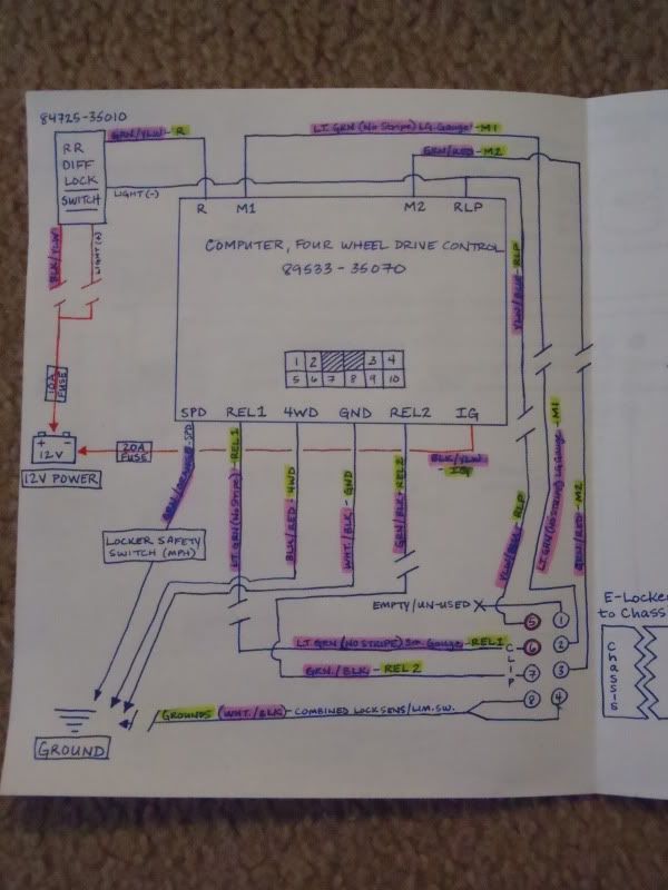
Well, since you pretty much copied the wiring diagram that I created & posted, I guess I'll go ahead and answer your question.

Judging by your diagram, you have taken the (IG) terminal on the ECU (black & white according to your diagram, mine was black/yellow), fused it at 20A and connected it to a ground point (battery negative terminal per your diagram).

You may have been confused by the way I drew my diagram (see below) as I have the (IG) terminal going to the battery, and I can see how it could appear that I'm trying to show it connecting to the negative terminal, however, the (IG) terminal should be connected to a 12V+ source. I thought that was made clear by the fact that the lead is fused (why fuse a ground lead?), and drawn in red, and the battery is labeled underneath as "12V power". Either way, I think that's your problem.

For a look at the factory diagrams, check out the E-locker links / diagrams / info post in my build thread...

http://www.toyota-4runner.org/3rd-g...one-2001-sport-ed-trd-scd-27.html#post1038490

793f5afa.jpg~original
 
Well, since you pretty much copied the wiring diagram that I created & posted, I guess I'll go ahead and answer your question.

Judging by your diagram, you have taken the (IG) terminal on the ECU (black & white according to your diagram, mine was black/yellow), fused it at 20A and connected it to a ground point (battery negative terminal per your diagram).

You may have been confused by the way I drew my diagram (see below) as I have the (IG) terminal going to the battery, and I can see how it could appear that I'm trying to show it connecting to the negative terminal, however, the (IG) terminal should be connected to a 12V+ source. I thought that was made clear by the fact that the lead is fused (why fuse a ground lead?), and drawn in red, and the battery is labeled underneath as "12V power". Either way, I think that's your problem.

For a look at the factory diagrams, check out the E-locker links / diagrams / info post in my build thread...

http://www.toyota-4runner.org/3rd-g...one-2001-sport-ed-trd-scd-27.html#post1038490

793f5afa.jpg~original

Yes I did copy yours. Thanks for that by the way. I honestly didn't pay attention to the red. Not the best when it comes to wiring up things. Hipefully that was my issue. How does it reverse the polarity for the locker to disengage?
 
Yes I did copy yours. Thanks for that by the way. I honestly didn't pay attention to the red. Not the best when it comes to wiring up things. Hipefully that was my issue. How does it reverse the polarity for the locker to disengage?

You're welcome. The ECU contains several small relays which are used to control the flow of power in the circuit. Power is fed into the e-locker motor on one of two alternating paths and there is a pair of limit switches in the e-locker actuator that switch the path to ground.
 
You're welcome. The ECU contains several small relays which are used to control the flow of power in the circuit. Power is fed into the e-locker motor on one of two alternating paths and there is a pair of limit switches in the e-locker actuator that switch the path to ground.

Came home and switched the wire to the positive side. BOOM!!!. Working like a charm. Even got the diff lock light to work also. Thanks again.
 

Members online

Forum statistics

Threads
278,316
Messages
3,554,120
Members
248,016
Latest member
Advally Service

Trending content

Back
Top