

LowellWatt
Junior Member
I wanted to share a wiring mod I came up with to get your late model 3rd gen (2001-2002) to recognize a Northwest Fab Eco Crawler install. This should also work for doing a straight j-shift transfer case swap, but with a simpler wiring scheme. This is going to be long-winded because I'm a millenial and I can't help myself. Hopefully someone finds this useful, or at least an interesting read. I posted a similar breakdown on Reddit with hardly any reception, so I'm aware there's a very limited audience for this mod.
DISCLAIMER: This modification requires cutting into the factory wiring harness. I'm not an electronics expert by any means, so there may be better way to do this. If you aren't comfortable with relays, splicing, and general autism, I wouldn't suggest this for a first dip in the pool. I'm not liable for any damage done to your vehicle as a result of attempting this mod.
I installed a NWF Eco Crawler some time ago and to nobody's surprise, you can't just splice the j-shift plunger switches into the factory harness and get the ECU to recognize the shift states. Late model 3rd gens all came with the latest version of the multi-mode case, which adds the "center diff lock" functionality to switch between AWD and 4WD. The problem is that the ECU needs to see more than just a 4WD circuit closed to work properly, so you can't just plug in the plungers on a j-shift case and expect it to recognize the different 4WD states. Because the ECU is looking for the factory components, the 4WD indicator on the dash will just flash indefinitely, and the front ADD won't engage on its own. The other side of this is that shifting into low range will not remap the transmission shift points like it should. RPMs climb much faster in low range, so with normal shift points the truck will get all herky jerky. Yes you can keep it in L or 2 to help with this, but I wanted to see if I could replicate the factory ECU conditions as closely as possible.
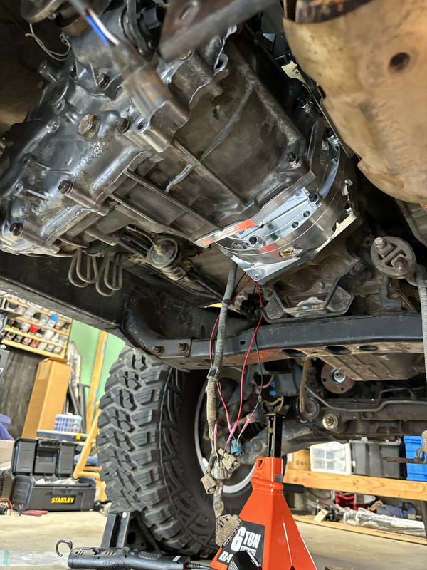
I searched for a long time to see if anyone had done this successfully, and I couldn't find anything other than some facebook comments that didn't go into any detail, or were flat out wrong. The service manual wiring diagrams are helpful, but the descriptions don't go into detail about which 4WD circuits are closed in different states. Where the earlier transfer cases had two 4WD states: H4 and L4; the late multi-mode cases have three: H4 (AWD), H4L (center locked), and 4L. Before I sold my original transfer case, I bench tested it to see which circuits were closed in the different actuator positions, and then came up with a plan to replicate it.
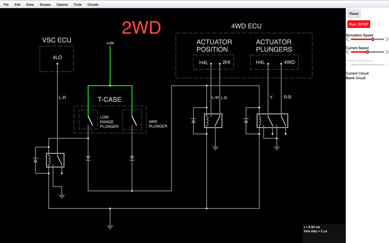
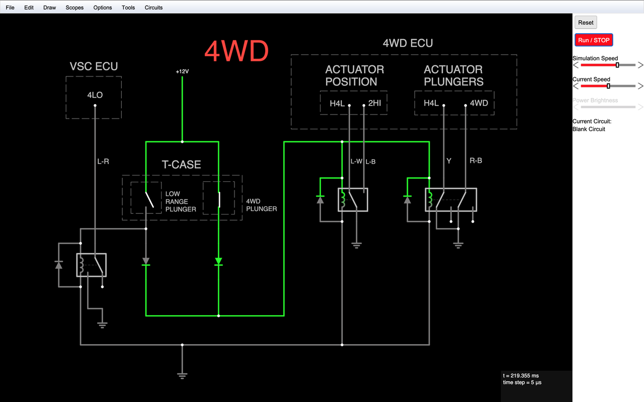
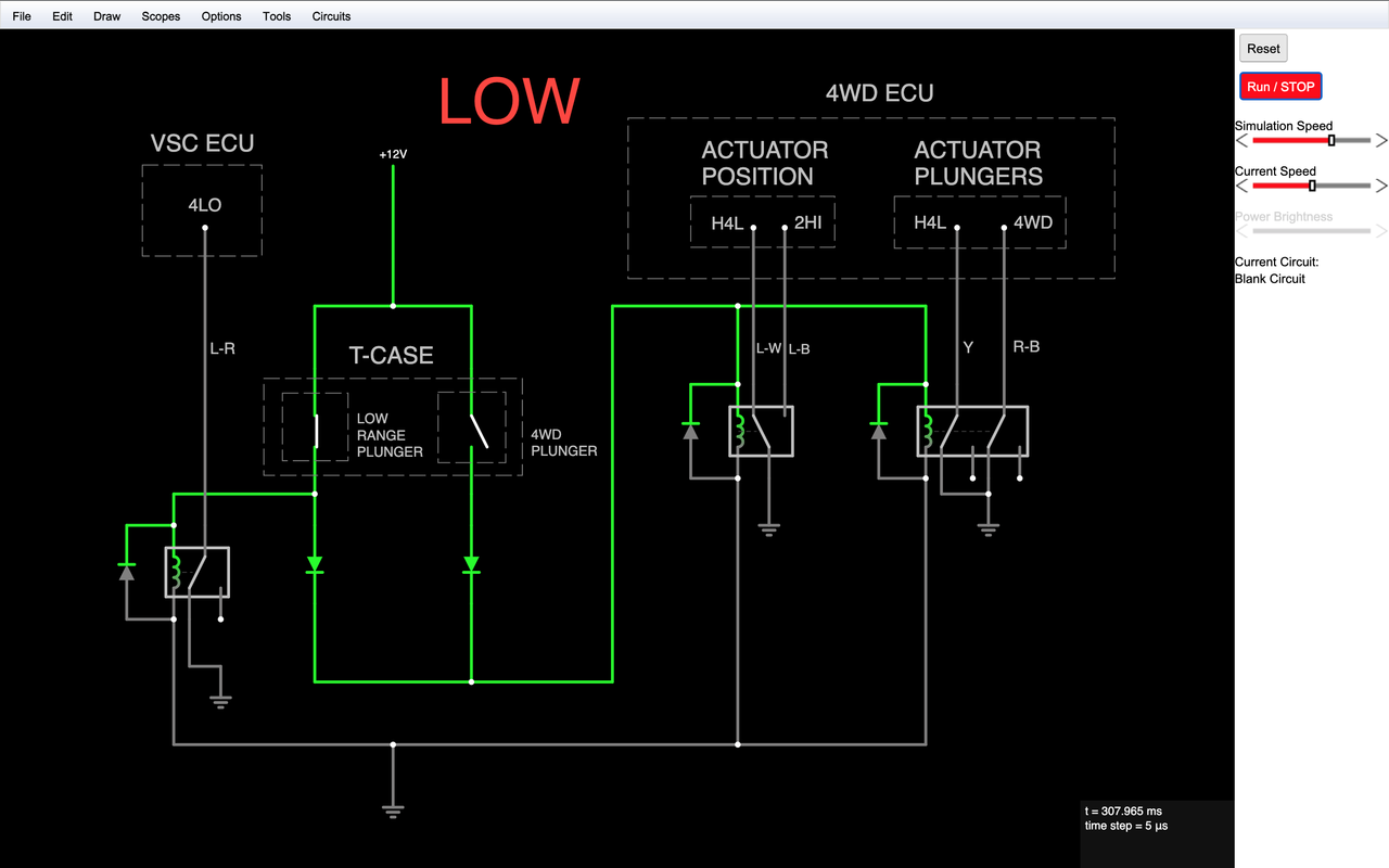
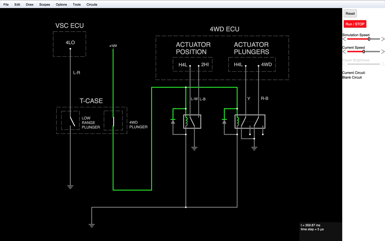
Here's the diagrams I came up with showing each shift state. The best way I figured to do this was to isolate the 4WD and low range plunger switch circuits from the ECU entirely. The plunger switches are fed from a switched 12V source and depending on position, will open or close relays to control the 4WD circuits. I designed it so shifting into low range on the transfer case will also engage the 4WD circuit, so it can run in 2L if needed. The diode on the low range plunger switch path prevents that circuit from being backfed when only the 4WD plunger is activated. This layout only allows either H4 or H4L to be used as the new standard 4WD state. I chose H4L because it disables the VSC.
2WD
4WD
Low range
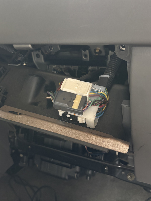
The procedure for this is as straightforward as it can be. Run 4 new wires for the plunger switches between the transfer case and the harness connectors above the glove box. The wires you need are mostly in the grey connector, and there's one in the big ass one with the lever lock.
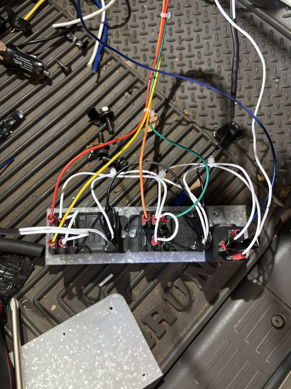
I wired the relays following the diagram and mounted them to a piece of plastic cutting board. There isn't a lot of room behind the dash but I was able to get it mounted to the dash support bar behind the airbag. It's a chore to get in and out so if you do it this way, make sure to test everything before shoving everything in there.
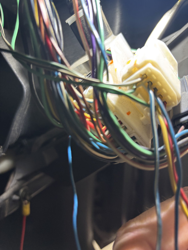
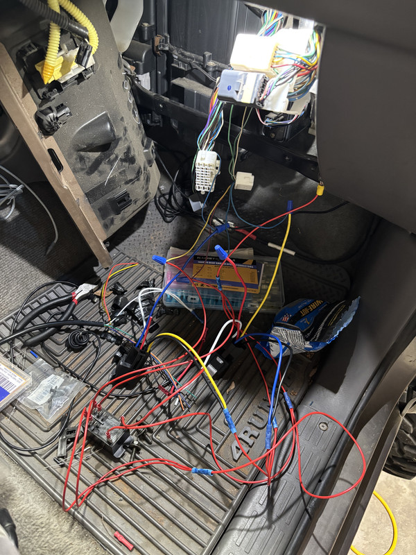
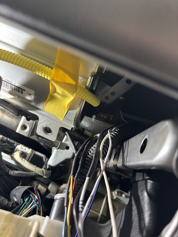
The first test worked with 4WD, but I couldn't get the ECU to chill out in low range. The indicator would just flash like it was waiting on a wiring state that I just couldn't figure out. I solved this by de-pinning the 4LO wire from the 4WD ECU behind the driver side kick panel. I tested again, and the ECU recognizes the low range state and remaps the transmission shifts like it should.
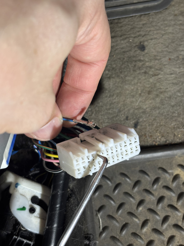
For anyone that just wants to do a straight j-shift swap, the wiring gets a little simpler because you can't shift into low range without first being in 4WD. Somebody hit me up on instagram asking about it, so I made a diagram that removes the low range relay and circuit pathways. The factory wiring for the low range plunger stays put, and you'd only need 2 new wires run up to the glove box. This is untested as of now but I don't see any reason it wouldn't work. You'll still need to de-pin the 4LO wire from the 4WD ECU same as the other setup.
Again I'm sure there's better ways to do this, but it solved my problem and I thought it might at least give someone a starting point. Let me know if you have questions or need clarity on anything.
DISCLAIMER: This modification requires cutting into the factory wiring harness. I'm not an electronics expert by any means, so there may be better way to do this. If you aren't comfortable with relays, splicing, and general autism, I wouldn't suggest this for a first dip in the pool. I'm not liable for any damage done to your vehicle as a result of attempting this mod.
I installed a NWF Eco Crawler some time ago and to nobody's surprise, you can't just splice the j-shift plunger switches into the factory harness and get the ECU to recognize the shift states. Late model 3rd gens all came with the latest version of the multi-mode case, which adds the "center diff lock" functionality to switch between AWD and 4WD. The problem is that the ECU needs to see more than just a 4WD circuit closed to work properly, so you can't just plug in the plungers on a j-shift case and expect it to recognize the different 4WD states. Because the ECU is looking for the factory components, the 4WD indicator on the dash will just flash indefinitely, and the front ADD won't engage on its own. The other side of this is that shifting into low range will not remap the transmission shift points like it should. RPMs climb much faster in low range, so with normal shift points the truck will get all herky jerky. Yes you can keep it in L or 2 to help with this, but I wanted to see if I could replicate the factory ECU conditions as closely as possible.
I searched for a long time to see if anyone had done this successfully, and I couldn't find anything other than some facebook comments that didn't go into any detail, or were flat out wrong. The service manual wiring diagrams are helpful, but the descriptions don't go into detail about which 4WD circuits are closed in different states. Where the earlier transfer cases had two 4WD states: H4 and L4; the late multi-mode cases have three: H4 (AWD), H4L (center locked), and 4L. Before I sold my original transfer case, I bench tested it to see which circuits were closed in the different actuator positions, and then came up with a plan to replicate it.
Here's the diagrams I came up with showing each shift state. The best way I figured to do this was to isolate the 4WD and low range plunger switch circuits from the ECU entirely. The plunger switches are fed from a switched 12V source and depending on position, will open or close relays to control the 4WD circuits. I designed it so shifting into low range on the transfer case will also engage the 4WD circuit, so it can run in 2L if needed. The diode on the low range plunger switch path prevents that circuit from being backfed when only the 4WD plunger is activated. This layout only allows either H4 or H4L to be used as the new standard 4WD state. I chose H4L because it disables the VSC.
2WD
4WD
Low range
The procedure for this is as straightforward as it can be. Run 4 new wires for the plunger switches between the transfer case and the harness connectors above the glove box. The wires you need are mostly in the grey connector, and there's one in the big ass one with the lever lock.
I wired the relays following the diagram and mounted them to a piece of plastic cutting board. There isn't a lot of room behind the dash but I was able to get it mounted to the dash support bar behind the airbag. It's a chore to get in and out so if you do it this way, make sure to test everything before shoving everything in there.
The first test worked with 4WD, but I couldn't get the ECU to chill out in low range. The indicator would just flash like it was waiting on a wiring state that I just couldn't figure out. I solved this by de-pinning the 4LO wire from the 4WD ECU behind the driver side kick panel. I tested again, and the ECU recognizes the low range state and remaps the transmission shifts like it should.
For anyone that just wants to do a straight j-shift swap, the wiring gets a little simpler because you can't shift into low range without first being in 4WD. Somebody hit me up on instagram asking about it, so I made a diagram that removes the low range relay and circuit pathways. The factory wiring for the low range plunger stays put, and you'd only need 2 new wires run up to the glove box. This is untested as of now but I don't see any reason it wouldn't work. You'll still need to de-pin the 4LO wire from the 4WD ECU same as the other setup.
Again I'm sure there's better ways to do this, but it solved my problem and I thought it might at least give someone a starting point. Let me know if you have questions or need clarity on anything.


