Exchanging the cable between battery and fuse box

Okki

New member
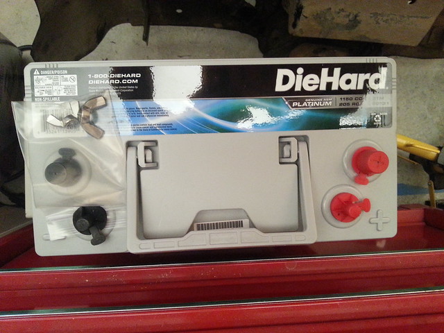
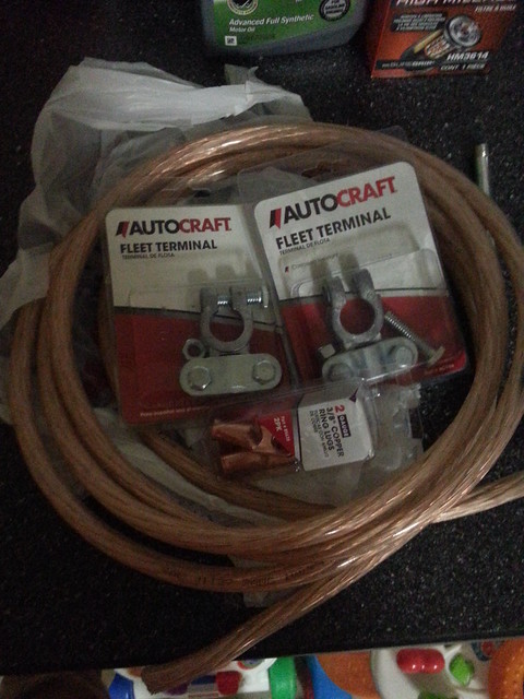
I picked up a Group 31 Marine battery and will be lengthening the cables going from the alternator to the battery to 2AWG. I'll be doing the same thing to the main ground cable.

I have a sneaky suspicion that I will also need to lengthen the wire that connects the battery to the OEM fusebox. has anyone had that apart and an inclination about how much pain and effort will be associated with making that change? I rather replace it as compared to splicing on an extension.
11159298894_f3aa31cbec_z.jpg
11159318184_b88b51a137_z.jpg


Thanks!

Okki
 
Register to hide this ad
I believe [MENTION=74569]SOcalTRAIL[/MENTION] has done it... He was having custom cable made while also looking at making battery trays for the 31
 
bumped for [MENTION=74569]SOcalTRAIL[/MENTION] input...

I did order a (cheap) hydraulic crimper on Amazon, so hopefully this weekend I'll get started with making the cables.

Okki
 
bumped for [MENTION=74569]SOcalTRAIL[/MENTION] input...

I did order a (cheap) hydraulic crimper on Amazon, so hopefully this weekend I'll get started with making the cables.

Okki

If you do end up going the cheap crimper route, it might not hurt to give it a quick dab of solder as well just for good measure. Problem is, achieving a proper crimp as a hobbyist is damn near impossible (especially with cheap tools and on fatter wires). In order to achieve a proper crimp, engineers go through a zillion calculations to ensure that the compressed copper pretty much fuses together into a cold welded joint.

With a little solder in addition to the crimp you will have an extra bit of security in your connection. Plus solder helps shield the exposed cooper from corrosion as well, which is always a plus in the engine compartment :)

IMO, worthwhile to look into if you've got the time.
 
bumped for [MENTION=74569]SOcalTRAIL[/MENTION] input...

I did order a (cheap) hydraulic crimper on Amazon, so hopefully this weekend I'll get started with making the cables.

Okki


I talked to Broadway Auto Electric ( a place up the street from my factory ) and they basically said it was no prob for them to do it, but I havn't had it done yet. They have all the bad ass cables, crimpers, and what not so I was just going to let them do the whole thing. I had my group 31 batt in for about a month and took it out to re-design the tray. I finished the new design but havnt had a second to put it back in. The day I do that I plan on dropping the truck off with the electric guys to lengthen the cables. I want to route the main ground a bit differently so it will probably need close to 8 inches added.

So many projects, so little time!
 
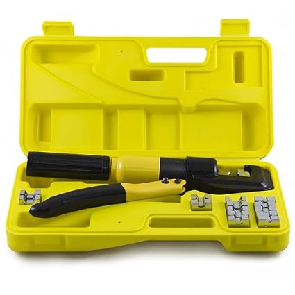
This is the crimper I got:

410oeUNyxiL._SX425_.jpg

10 Ton Hydraulic Wire Battery Cable Lug Terminal Crimper Crimping Tool 9 Dies - Amazon.com

thanks for the suggestion on the solder [MENTION=85512]eddiebx[/MENTION]. I'll do that on both the crimped and the fleet terminal side.

Okki

PS: for those who don't know a fleet terminal. Mine only have 2 bolts instead of 4, but same principal beyond that:
880M.jpg

Nice looking cripmer. I'll second what [MENTION=85512]eddiebx[/MENTION] said about soldering. Definitely a good idea to flow some solder in there.

Subscribed to see your final product! Nice work!
 
This is the crimper I got:

410oeUNyxiL._SX425_.jpg

10 Ton Hydraulic Wire Battery Cable Lug Terminal Crimper Crimping Tool 9 Dies - Amazon.com

thanks for the suggestion on the solder [MENTION=85512]eddiebx[/MENTION]. I'll do that on both the crimped and the fleet terminal side.

Okki

PS: for those who don't know a fleet terminal. Mine only have 2 bolts instead of 4, but same principal beyond that:
880M.jpg

That actually looks like a badass crimper and at a great price! Gotta love amazon! Heck, you might even be able to get away with not bothering with the soldering if the crimp comes out pretty sound :)
 
That actually looks like a badass crimper and at a great price! Gotta love amazon! Heck, you might even be able to get away with not bothering with the soldering if the crimp comes out pretty sound :)

Yeah.. but the dies are metric, so getting a good 2AWG crimp will still be a bit of a challenge. but as you said.. for the price you can't really knock it.

Okki
 
I used the same crimper from Harbor Frieght...oh the horror....it f'in rocked.


It worked great and I actually cleaned up inside of the copper crimp prior to soldering, and hit it with electric solder...NOT plumbing...I forget the difference, but there is one.

Just a side note....the solder will "creep" up the wire invariably..so minimize the amount just to the lug.
 
I used the same crimper from Harbor Frieght...oh the horror....it f'in rocked.


It worked great and I actually cleaned up inside of the copper crimp prior to soldering, and hit it with electric solder...NOT plumbing...I forget the difference, but there is one.

Just a side note....the solder will "creep" up the wire invariably..so minimize the amount just to the lug.

Great point Pat! It mainly has to do with the type of flux core, I think the plumbing version is a big no no and will cause corrosion, you want to stick with rosin core. Try to get a 60/40 leaded solder if you can. I know lead is bad for us, but good for keeping the joint a bit more durable. Lead-free is a wee bit more brittle, and not ideal for higher vibration environments.

One way to minimize the solder from wicking upwards into the wire is to keep the heat concentrated down low at the lug; and keep the open end of the lug facing upwards since solder flows towards the heat and gravity. Some will still wick up inevitably, but you'll live :)
 
REMOVE WIRING HARNESS CLAMP BRACKET
(a) Detach the c lamp.
(b) Remove the bolt and wiring harness clamp bracket.
10. REMOVE NO. 2 EXHAUST MANIFOLD HEAT INSULATOR
11. REMOVE GENERATOR ASSEMBLY
(a) Open the terminal cap.
(b) Remove the nut and disconnect the wire harness from terminal B.
(c ) Disconnect the generator connector from the generator assembly.
(d) Remove the 2 bolts and disconnect the wire harness.
(e) Disconnect the wire harness c lamp.

The above instructions come from page 2743 of the PDF'ed repair manual. they are steps included in the removal of the alternator (generator they call it).

Not sure what the wiring harness in step 11 A and B is and if I need to worry about it. I think 11 D is the location that I'm really looking for. I'm guessing one is ground and the other power.

Okki
 
REMOVE WIRING HARNESS CLAMP BRACKET
(a) Detach the c lamp.
(b) Remove the bolt and wiring harness clamp bracket.
10. REMOVE NO. 2 EXHAUST MANIFOLD HEAT INSULATOR
11. REMOVE GENERATOR ASSEMBLY
(a) Open the terminal cap.
(b) Remove the nut and disconnect the wire harness from terminal B.
(c ) Disconnect the generator connector from the generator assembly.
(d) Remove the 2 bolts and disconnect the wire harness.
(e) Disconnect the wire harness c lamp.

The above instructions come from page 2743 of the PDF'ed repair manual. they are steps included in the removal of the alternator (generator they call it).

Not sure what the wiring harness in step 11 A and B is and if I need to worry about it. I think 11 D is the location that I'm really looking for. I'm guessing one is ground and the other power.

Okki

On most japanese alternators I've seen, the heavy gauge charging cable is usually bolted directly to the terminal on the side of the alternator...it sounds like that might be what you're removing in step 11a-b?
 
I picked up a Group 31 Marine battery and will be lengthening the cables going from the alternator to the battery to 2AWG. I'll be doing the same thing to the main ground cable.

I have a sneaky suspicion that I will also need to lengthen the wire that connects the battery to the OEM fusebox. has anyone had that apart and an inclination about how much pain and effort will be associated with making that change? I rather replace it as compared to splicing on an extension.

11159298894_f3aa31cbec_z.jpg
11159318184_b88b51a137_z.jpg


Thanks!


Okki

Okki is that wire stereo wire? I would use wire from McMaster Carr, or go to a local welding supply shop and buy wire designed for welding leads...they're designed for maximum amperage. The stranding definitely has something to do with the amount of amps flowing through.
 
I suggest you do not try to solder (tin) the end of the wire. Crimp type terminals are designed to hold the wire in the crimped area by deforming the barrel end the wire is inserted into. This means the strands of wire will be deformed into the crimp inside the barrel. If you tin the end, it will become stiffer and resist the crimping process - possibly resulting in a defective crimp with internal gaps that will impede current flow. Also this large of wire will not tin easily. Solder will wick up the end if you can even get it hot enough. For smaller wires that are connected by soldering anti wicking tools are used to prevent this as mil-spec soldering does not allow any wicking up under the insertion. Use a proper crimper with the correct dies and you will be fine. Strip the insulation so that when the wire is inserted into the terminal there is a small gap (1/16 inch max) between the end of the terminal and insulation. To make it a little neater you can slide some heat shrink on and slide it down over the crimp and shrink. You can also label cables this way using clear heat shrink. Just stick a label on the wire and place the clear heat shrink over it and shrink down. It will make a waterproof label for any size wire.
 
I suggest you do not try to solder (tin) the end of the wire. Crimp type terminals are designed to hold the wire in the crimped area by deforming the barrel end the wire is inserted into. This means the strands of wire will be deformed into the crimp inside the barrel. If you tin the end, it will become stiffer and resist the crimping process - possibly resulting in a defective crimp with internal gaps that will impede current flow. Also this large of wire will not tin easily. Solder will wick up the end if you can even get it hot enough. For smaller wires that are connected by soldering anti wicking tools are used to prevent this as mil-spec soldering does not allow any wicking up under the insertion. Use a proper crimper with the correct dies and you will be fine. Strip the insulation so that when the wire is inserted into the terminal there is a small gap (1/16 inch max) between the end of the terminal and insulation. To make it a little neater you can slide some heat shrink on and slide it down over the crimp and shrink. You can also label cables this way using clear heat shrink. Just stick a label on the wire and place the clear heat shrink over it and shrink down. It will make a waterproof label for any size wire.


Good points for sure..

I only soldered it after it was crimped and prior to the heat shrink wrap
 
Okki is that wire stereo wire? I would use wire from McMaster Carr, or go to a local welding supply shop and buy wire designed for welding leads...they're designed for maximum amperage. The stranding definitely has something to do with the amount of amps flowing through.

That was the only 2AWG cable I could find. Came from Advance Auto Parts. I told them what I was planning on using it for, and that's what they came up with. Never heard of McMaster Carr or if they have a location near me. No idea on welding shops either.

Of course question 2 is: How much difference would your suggested cable make? Right now i'm still running a stock alternator and likely will for some time. This is more prep for later on. and not sure if it would be a noticeable difference then?!?

I'll take any education you can give me on the topic.

Okki
 
Mcmaster Carr is a mail order company...comes in 1-2 days

Here's the cable, comes in Red or Black

McMaster-Carr

Look under the "Battery Cable" section

As far as the strands and winding, I don't have recollect the exact reference, but it stopped me from getting standard stuff. Something about the more wires, the more amps, but again, I'll see if I can find it.

I used this product for the dual battery install, and the winch install.
 
Since I need to get my battery in before I park my truck at the airport for a week, I will just run with the cable I have now. It's still better than stock. If I switch to a high output alternator I will at least know what I'm doing and I'll change out the cable at that point to the welding cable.

Based on what the McMaster website says, the thinner strands allow higher amps (147 vs 190) compared to the non-high flex cable.

Great suggestion though for anyone working on a dual battery setup.

Okki
 

Members online

Forum statistics

Threads
278,311
Messages
3,554,082
Members
248,016
Latest member
Advally Service

Trending content

Back
Top