I found a fix for my 2006 Limited V6 cluster gauge failure. It is different than above. As mentioned I had no tac, speed, fuel, temp or odometer gauges working. The drive selector only flickered softly in reverse and none of the others displayed. i did change out the grounds that go on the drivers side rear of the engine compartment but that did not work unfortunately.
At first I thought it was my instrument cluster and removed it and had it tested and it was fine. The guys wiring diagrams helped me.
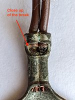
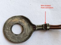
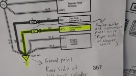
I played around with the instrument cluster and found when I touched ground (metal bar in dash) with my voltmeter to ground to C13 (pictures to come) it worked and showed 12.6 when off and 14.6 when running. That pin has no connector being used on eith side of it so slipping off of it was not as much a worry, esp when testing with a wire. Somewhere between the wire in the connector at the cluster and where it eventually goes outside to the engine block there must be some junction where it has failed. The wire gauge of the wires going to the engine block are thicker than those coming out of the cluster and they have thicker insulation.
After the voltmeter test I ended up testing it out with an 18 gauge stranded wire from the metal bar in the dash at the drivers left vent area to the same pin and when running my cluster lit up and the tac gauge moved. Success!
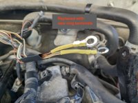
So I ended up crimping a ring terminal on one end of the wire and placed it under the screw at the vent and then stripped t about an inch of insulation of the ground wire about an 1 1/2” down from the connector. I thought about trying to insert it into the connector but did not want to mess up any of the other wires and it is a process opening them up. I wrapped the new line around the exposed ground and soldered it in and then wrapped it with electrical tape.
Please note when reassembling the circuit board to the black dash plate be very careful as there are about 20 odometer pins that have to be lined up. It took three times to get it right and I had two bent pins. Luckily after straightening they went in and all works fine. Look up instrument cluster removal on youtube and you will find videos on that.
Even though I noted where the gauges all sat I had to redo them. For RPM I have an OB2 scanner so I could match that to the rpm and remove and attach the dial , when off lol and try again. For the speedometer I set it to zero and went for a drive at 30 and 50 mph and using Waze navigation which shows speed I could see where I was out and stop and remove dial and move it one way or the other and this only took a couple of tries. I also did the fuel tank by filling it and making sure my meter was showing just past full. As for the temp, that one I left just around the C mark and it goes similar to where it went before. You can attach the bottom black part of the cluster and the clear outer part with the cluster installed. It is all clips except for two screws up top.
Before I found this simple solution AI had me thinking it was the ignition switch ( at the base) I guess which can go but it tested fine. One other possibility was a ground failure in the fuse panel by your left knee. This thing is a rubrics cube of wires and costs around 2k so that wasn’t happening. Long story short….check your wiring first before it’s a parts bomb. Also, you will mostly like need to clear the P0500 speed sensor code which went off because the computer did not know the vehicles speed.
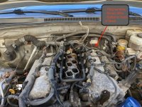
These are the grounds I redid that went to the back of the drivers side of the engine bay. It didn’t help me but it helped others.
sorry for the picture order mess up…. once I hit accept it all changed
This is the circuit board with the pins showing. This is how my cluster specialist tested it and please remember it rotates 180 degrees so that connector is just right of centre when attached.
Here C13 is ground. C15 and C5 have power when the engine is on. C16 has constant power, even when the engine is off. Wiring diagram to follow.
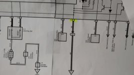
Wiring diagram shows C13 is ground going to EE (engine block). and shows C16 as always hot and C15 and C5 as power on start up.
This is board plugged in with me testing it. I have tac dial attached.
Here is a closer look. I touched voltmeter to ground on dash and to the pin and got my reading. then tested with wire which completed the circuit and lit all up. Remember the pins on either side of it on mine had no connection to anything.
Here is the back half of the connector flipped upward 180 degrees so I could get to the ground wire. I had to remove some electrical tape that was around the bundle. Please note that these connectors pop out of their holders and when getting ready to assemble you have to position them there and the two bolts in the top of the cluster pull the back of the connector into the pins of the circuit board. Don’t try to overtighten this..just snug.
Here you see the wire attached under the vent screw and ending up in the ground wire at the connector where it was soldered in.