FMU Compass Calibration **fixed**

Devbot

New member
P0500 and calibration issues were fixed by finding a short in the speed sensor wire going down the A-pillar. Splice was also moved from ABS unit to ECU (plug E12 pin 22, green-orange wire)

Hey all
Finished installing a field monitor unit this weekend and I can't seem to get the compass to work, which is constantly reading NE. Every other function works flawlessly. I've followed the instructions by pressing the adjust button and driving in circles while it flashes, but nothing happens - after a minute the compass merely stops flashing while staying in it's NE position, and does not give me an error message (flashing car symbol.) I've tried turning fully locked, in big circles, slow, fast, tried it in town, out in the farmlands, to the left, to the right - must've tried a dozen times now to no avail and I really can't think of any other combination. Holding the adj button for 5+ seconds like the Subaru units doesn't offer anything, and the Left/Right gauges on the sides don't even light up like they sure during calibration
Anybody have an idea? It seems like many have trouble getting their compass working at first but get it going after a few tries, but that doesn't seem to be happening here. Maybe a dying wheel speed sensor? (grn/org FMU wire spliced into the blu/gry ABS wire like most people)
Getting real dizzy over here! :crazy:
 
Last edited:
Register to hide this ad
Welp, think I found my issue; driving to work today I got a CEL and my speedometer stopped working completely :boink: Hope it's just the wheel speed sensors
 
Puzzled as to why you think the speed sensors are related to the compass? If the scrolling green bars when moving forwards or back aren't working I would understand. The compass should change coordinates out the box. The 360 degree thing is just to identify true North. Curious.
 
Puzzled as to why you think the speed sensors are related to the compass? If the scrolling green bars when moving forwards or back aren't working I would understand. The compass should change coordinates out the box. The 360 degree thing is just to identify true North. Curious.

I thought I read the compass was reliant on the speed sensors to work properly, and that's why we splice the wires together as opposed to running it on any old 12v line.
You are correct in saying the green bars aren't working either, sorry I didn't point that out. Currently it's just the temp, altitude, and barometer that are functional. And strangely enough today when I got to work and started my car again on break, the compass has orientated itself to SW - the direction I was facing when parked. It seems like the compass will adjust only after turning the car off and on again
To boot my odometer isn't working now, along with the speedometer
 
Puzzled as to why you think the speed sensors are related to the compass? If the scrolling green bars when moving forwards or back aren't working I would understand. The compass should change coordinates out the box. The 360 degree thing is just to identify true North. Curious.
Yes, but it needs to know the vehicle is moving to update the direction heading.

-Charlie
 
OBD code is "P0500 - Vehicle Speed Sensor A." Gonna start probing resistance while I'm at it but if anyone has any advice otherwise I'd love to hear it; a quick search shows nearly every thread to be a dead end, typical "Hey guys I'm having this problem - oh wait nevermind, fixed itself. Bye!"
Edit: got no signal at both the FMU plug or the ABS plug. Cracked open the ABS module and didn't see anything melted or corroded, looked pristine as ever.
I see lots of debate between what sensor can cause this - whether it be VSS-A (ABS sensors) or VSS-B (trans speed). Some insist that VSS-B has absolutely positively nothing to do with the speedometer, but it seems very unlikely that it works solely off the ABS sensors...
 
Last edited:
have you tried disconnecting the FMU and test if the speedometer works and the P0500 code disappears?
the speedometer on most Hilux Surfs are connected to the speed sensor attached to the rear of the transfer case, but then there are many USDM 4Runners that have the FMU with no issues, perhaps you connected the wrong wire to the correct wire or connected the connected the correct wire to the wrong wire?
 
Last edited:
have you tried disconnecting the FMU and test if the speedometer works and the P0500 code disappears?
the speedometer on most Hilux Surfs are connected to the speed sensor attached to the rear of the transfer case, but then there are many USDM 4Runners that have the FMU with no issues, perhaps you connected the wrong wire to the correct wire or connected the connected the correct wire to the wrong wire?

Problem still perists even with the FMU unplugged.
I very highly doubt I got the wrong wire, seeing as the speed sensor wire is the only blue/gray wire in the entire ABS unit. And i think its safe to say if I didnt get the right one, I wouldn't be having issues with the speed sensors specifically and would have other ABS issues
 
hey

just read you post.

The FMU doesn't require speed signal to calibrate the compass. Speed is only for the unit to know when the car is moving to understand how to display barometric pressure correctly since barometric pressure is used for both to get a picture of how the weather changes while the car is stationary, and also for informing the altitude changes, which happens only when the car is moving. Hence the need for speed signal.

My concern is if you have not connected the 12V+ constant and 12V+ thru ignition wire correctly, since the unit will forget compass calibration if it loses power thru the constant 12V+ on pin 1 on the connector. May be you have connected both 12V+ thru ignition power.

The unit should calibrate when you make a 360 degree turn or do 4 point reverse turn. The idea is to just rotate the unit so the compass finds thru magnetic north, as stated above.

Is the FMU OEM?
 
hey

just read you post.

The FMU doesn't require speed signal to calibrate the compass. Speed is only for the unit to know when the car is moving to understand how to display barometric pressure correctly since barometric pressure is used for both to get a picture of how the weather changes while the car is stationary, and also for informing the altitude changes, which happens only when the car is moving. Hence the need for speed signal.

My concern is if you have not connected the 12V+ constant and 12V+ thru ignition wire correctly, since the unit will forget compass calibration if it loses power thru the constant 12V+ on pin 1 on the connector. May be you have connected both 12V+ thru ignition power.

The unit should calibrate when you make a 360 degree turn or do 4 point reverse turn. The idea is to just rotate the unit so the compass finds thru magnetic north, as stated above.

Is the FMU OEM?
Yes, it's an OEM FMU, not a Subaru one.
The issue is not that it's LOSING compass calibration, the compass is not functioning period. If anything I'd say it's keeping whatever calibration it has, as the compass will orientate itself to the correct position after the car is shut down and restarted, but during operation is does not move or react whatsoever. If I park the car facing east, shut it down and walk away, the compass will read east when I come back to it, regardless of whatever it was reading when I parked it.
I followed this wiring to the letter - the same set up as everyone else - if I did it wrong so has every other person. Doesn't seem likely to me
Edit: actually now that I think about it, I spliced in at the ABS unit whereas others like Ripcord spliced in at the ECU, I wonder if that has anything to do with it...
 
Last edited:
Did you connect to the speedo signal between the ABS unit and the gauge cluster or the speedo signal between the cluster and ECU?

If you used the signal between the ABS ECU and the cluster, change it to use the signal *after* the cluster. It is 'cleaned up' by the cluster for the ECU. Tapping off the pre-cluster signal may ruin the signal quality for the cluster and cause the problem you are seeing.

I still think that if the FMU doesn't have a speedo signal toggling, it won't update the compass display (you wouldn't want your compass to change reading while stopped, right? - and it did update upon power-up when pointing a different direction, so it is making a reading)

-Charlie
 
Did you connect to the speedo signal between the ABS unit and the gauge cluster or the speedo signal between the cluster and ECU?

If you used the signal between the ABS ECU and the cluster, change it to use the signal *after* the cluster. It is 'cleaned up' by the cluster for the ECU. Tapping off the pre-cluster signal may ruin the signal quality for the cluster and cause the problem you are seeing.

I still think that if the FMU doesn't have a speedo signal toggling, it won't update the compass display (you wouldn't want your compass to change reading while stopped, right? - and it did update upon power-up when pointing a different direction, so it is making a reading)

-Charlie
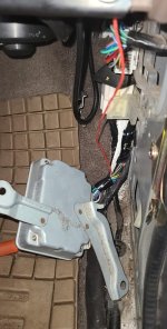
I believe I would've tapped it before the gauge cluster, so it's good to hear I might be on the right track. In a few minutes I'll clock out for lunch and get a picture of exactly where, since I have things torn apart currently
 
The red wire hanging down is the one leading from the FMU, with the solder sleeve directly under that strip of tape. Just to give an idea of where it's spliced
 

Attachments

  • Snapchat-1325638542.jpg
    Snapchat-1325638542.jpg
    141.1 KB · Views: 467
Bingo. The signal there is very sensitive and shouldn't be tapped there. The speedo signal out from the cluster is available in multiple other places in the truck. At the ECU, at the diff lock ECU plug, etc.

-Charlie
 
Bingo. The signal there is very sensitive and shouldn't be tapped there. The speedo signal out from the cluster is available in multiple other places in the truck. At the ECU, at the diff lock ECU plug, etc.

-Charlie

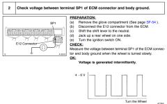
I would love to give it a try... Only problem is I can't find that same wire anywhere at my ECU. I see a few white/blue wires, a solid gray or two, but the gray/blue found at the ECU is nowhere to be found. When going off the FSM section regarding P0500, they say the speed sensor should be located at this pin on the right-most plug (pic below) - but what I find there is a solid purple wire. Not sure how much I should trust the FSM, seeing as there were multiple ECUs used but makes no mention of it... I saw a 10 year old post here saying it should be a green/orange wire at the same plug, but I still come up short there - only have green/yellow. I suppose downloading a proper pinout would be in order
I would take a picture of what I'm seeing (or lack thereof) but it's impossible to get a clear shot of everything and I'm not sure it's totally necessary
 

Attachments

  • p0500.PNG
    p0500.PNG
    69.6 KB · Views: 505
Last edited:
Do you have a wiring diagram for your year? It should have a pin chart for all the ecu plugs that will tell you what wire you need. On mine the wire going to the ecu from the cluster was not the same color as the wire going from the speed sensor to the cluster
 
Do you have a wiring diagram for your year? It should have a pin chart for all the ecu plugs that will tell you what wire you need. On mine the wire going to the ecu from the cluster was not the same color as the wire going from the speed sensor to the cluster

Looking at the ECU pinout right now and it arguably provides less information than the previously posted image. This is the best and only piece of information it could give me
These wires I DO have in those locations... but now it's a choice/deduction between the two I guess. If anything I would assume the green/orange wire in E12?
 

Attachments

  • fsmecm.PNG
    fsmecm.PNG
    10.6 KB · Views: 165
Last edited:
That seems correct, to double check and make sure find the same wire on the ecu diagram it should be listed as coming from the combination meter
 
That seems correct, to double check and make sure find the same wire on the ecu diagram it should be listed as coming from the combination meter

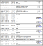
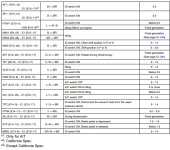
No such information exists on the diagram. You're very optimistic about what the pinout tells you - allow me to show just how little it entails. As you can see, 75% of the words on the page are either IG+A/C SWITCH ON/OFF or "Idling"
If it won't even mention speed sensors by name, it seems like the chances of the combination meter being mentioned are very slim
Edit: Now that I look at it, the brown wire/pinout location they're referring to - "E1 (E10-17)" - is mentioned a hell of a lot. And I'm gonna take a wild, left field guess and say the "SP" is short for speed
 

Attachments

  • fsmecm1.PNG
    fsmecm1.PNG
    86.4 KB · Views: 162
  • fsmecm2.PNG
    fsmecm2.PNG
    68.8 KB · Views: 159
Last edited:
Is this from the factory service manual or the separate electrical wiring diagram? The diagram I have for my 97 is much more in-depth, unfortunately I only have 97 and 99 diagrams but when I get a chance I’ll look at the 99 diagram and see if it’s close enough to yours to give any insight
 

Members online

No members online now.

Forum statistics

Threads
278,306
Messages
3,554,045
Members
248,016
Latest member
Advally Service

Trending content

Back
Top