Fuel Tank Relocation (and new Rear Bumper design)

Thanks guys!!

It runs great. Had a minor leak at one of my fittings just needed to tighten it more. First time it’s ran in 7 months!!
 
I've got a question on the filler neck/hose, specifically about the venting. Now the fuel tanks have a opening for the filler hose, but nothing to vent the tank during fuel-ups. From the tank swaps I've seen, it seems most people are adding an air vent line to the tank which obviously requires a little fabrication to the tank:

i-xR6SrH6-M.jpg


I read of some people using an internally vented fuel hose but I'm having a hard time understanding exactly how that works or where to get that. I imagine an internally vented filler hose requires a new filler neck compatible with that type of hose, correct? Is there a filler neck that fit's nicely in the OEM location?

I'm just trying to figure out the cleanest/easiest way to do this. Thanks in advance!
 
I've got a question on the filler neck/hose, specifically about the venting. Now the fuel tanks have a opening for the filler hose, but nothing to vent the tank during fuel-ups. From the tank swaps I've seen, it seems most people are adding an air vent line to the tank which obviously requires a little fabrication to the tank:

i-xR6SrH6-M.jpg


I read of some people using an internally vented fuel hose but I'm having a hard time understanding exactly how that works or where to get that. I imagine an internally vented filler hose requires a new filler neck compatible with that type of hose, correct? Is there a filler neck that fit's nicely in the OEM location?

I'm just trying to figure out the cleanest/easiest way to do this. Thanks in advance!

I added an external vent line. Basically what I did was cut the stock filler neck then used 2 90 degree fuel filler hose with a coupler between them and attached them to the filler on the tank. Then I found a hose barb to the size I wanted, drilled a hole at the top most point I could in the side with the filler neck then reached in and put a nut on the threaded end of the barb. I used JB weld to seal everything and pressure tested it. Everything works just fine. If you go the internally vented route check out fillernecksupply.com
You’ll find what you need there
 
This is the fuel gauge calibrator I'm using. With a aftermarket floatless fuel level sender.

Actually wiring up the classic instruments this week/weekend since I got all the plumbing finished up. Plan is to run the necessary signals through a DPDT switch and a 25A DPDT relay. Just need to research tying into the low fuel light.

Hey did either of you guys get your gauge calibrators to work? I’ve been struggling with the Tanks inc one. I’ve tested all my connections and wiring with a test light and multi meter. Everything tests ok but when I try to calibrate the gauge I get nothing. I’ve seen some of these on the market that say analog style gauges only and I have a feeling that the Tanks inc one is for analog even though it doesn’t say. Just wondering if you guys had any luck otherwise I’m just gonna buy a new gauge for the ford pump.

Is the stock fuel gauge a stepper motor? Or is it really analog? I’m just frustrated
 
Last edited:
[MENTION=106706]MN4runnerman[/MENTION] EDIT! I may have over looked that this seems to be a "stepper or digital" fuel level set up running a positive voltage drop/loop. :sorry: I'm going to confirm this tomorrow in a few hours (1:30am here lol). If this is the case then to my knowledge no fuel sender calibrators will work, since they only operate on a ground type system.

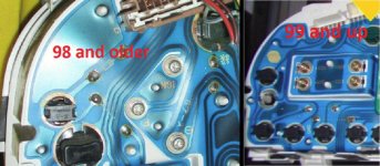
I think the year split for this whackie cluster is 99 and up, 98 has rolling odo/trip vs the 99+ digital odo/trip. Damn I may have shot myself in the foot, firetruck! But aircraft senders might work but they start at 450$ and up, yeah no thanks.


99 and up it's a 4 pin gauge vs. the 98 and older 3 pin simple and always works gauge grrr. So that tells me it's not normal lol. Usually they are 3 pins, 12v pos, signal and ground (most of them that is). And the low fuel light circuit is completely separate. On mine is COS- SIN- COS+ SIN+, so that tells me its stepper or digital.

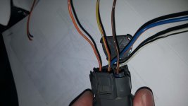
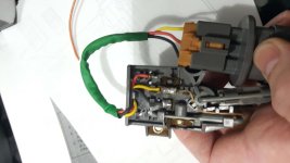
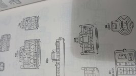
Seems any voltage to/from the sender calibrator on the gauge and/or the sending unit kills the calibrator module :( There are 3 smaller wires (once again on my 2000) that are as follows:

Orange - low fuel light (don't know what voltage but it's positive going into the low fuel sensor).
Yellow/red - signal from gauge ecm to fuel sender (might be + voltage from cluster ecm).
Brown/black - from fuel level sensor to cluster ecm (signal in [might be + voltage through sender]).

The are located on D connector (C28 blue 12 pin, pins 4, 5 and 6). See the pics attached.

 

Attachments

  • 20200515_215157_compress98.jpg
    20200515_215157_compress98.jpg
    127.6 KB · Views: 399
  • 20200515_215131_compress18.jpg
    20200515_215131_compress18.jpg
    124.5 KB · Views: 398
  • 20200515_215456_compress4.jpg
    20200515_215456_compress4.jpg
    126.4 KB · Views: 377
  • 5-16-2020 2-16-35 AM.jpg
    5-16-2020 2-16-35 AM.jpg
    112.4 KB · Views: 386
Last edited:
[MENTION=106706]MN4runnerman[/MENTION] EDIT! I may have over looked that this seems to be a "stepper or digital" fuel level set up running a positive voltage drop/loop. :sorry: I'm going to confirm this tomorrow in a few hours (1:30am here lol). If this is the case then to my knowledge no fuel sender calibrators will work, since they only operate on a ground type system.

I think the year split for this whackie cluster is 99 and up, 98 has rolling odo/trip vs the 99+ digital odo/trip. Damn I may have shot myself in the foot, firetruck! But aircraft senders might work but they start at 450$ and up, yeah no thanks.


99 and up it's a 4 pin gauge vs. the 98 and older 3 pin simple and always works gauge grrr. So that tells me it's not normal lol. Usually they are 3 pins, 12v pos, signal and ground (most of them that is). And the low fuel light circuit is completely separate. On mine is COS- SIN- COS+ SIN+, so that tells me its stepper or digital.

Seems any voltage to/from the sender calibrator on the gauge and/or the sending unit kills the calibrator module :( There are 3 smaller wires (once again on my 2000) that are as follows:

Orange - low fuel light (don't know what voltage but it's positive going into the low fuel sensor).
Yellow/red - signal from gauge ecm to fuel sender (might be + voltage from cluster ecm).
Brown/black - from fuel level sensor to cluster ecm (signal in [might be + voltage through sender]).

The are located on D connector (C28 blue 12 pin, pins 4, 5 and 6). See the pics attached.


Yeah I tried both the yellow/red and brown/black with absolutely zero luck. Then I did more research and think that this is a digital/stepper motor gauge and won’t work. I ordered an A pillar gauge pod and a nice looking auto meter fuel gauge. That’s the only way I think I’ll get it to work haha. Oh well my wiring is all spliced up. I guess 99 and up this won’t work
 
Yeah I tried both the yellow/red and brown/black with absolutely zero luck. Then I did more research and think that this is a digital/stepper motor gauge and won’t work. I ordered an A pillar gauge pod and a nice looking auto meter fuel gauge. That’s the only way I think I’ll get it to work haha. Oh well my wiring is all spliced up. I guess 99 and up this won’t work
The gauge itself on the dash is digital, but it is driven from the circuit board on the back of the cluster. The fuel sender in the tank should still be a "normal" setup. Here's what I found in the FSM:

0WQgJNm.jpg


-Charlie
 
The gauge itself on the dash is digital, but it is driven from the circuit board on the back of the cluster. The fuel sender in the tank should still be a "normal" setup. Here's what I found in the FSM:

0WQgJNm.jpg


-Charlie

What year FSM is this?

My 1999 FSM sender gauge resistance values are totally different...
i-SmsBgHp-X3.jpg


I'm actually very surprised by both FSM resistance values as I thought all Toyota senders were 90 ohm (empty) to 0 ohms (full). Maybe that only applies to earlier model Toyotas?

[MENTION=106706]MN4runnerman[/MENTION] [MENTION=405460]2TH4IST[/MENTION] maybe try working with these values instead?
 
What year FSM is this?

I'm actually very surprised by both FSM resistance values as I thought all Toyota senders were 90 ohm (empty) to 0 ohms (full). Maybe that only applies to earlier model Toyotas?

[MENTION=106706]MN4runnerman[/MENTION] [MENTION=405460]2TH4IST[/MENTION] maybe try working with these values instead?
It is called out as a for a 2000 (digital copies). I have a hard copy for my '99 but haven't referenced it for this.

Those numbers look like the voltage on connector with it plugged in and powered instead of resistances. They mixed units there, so there is something wrong. The numbers I posted look more realistic.

-Charlie
 
It is called out as a for a 2000 (digital copies). I have a hard copy for my '99 but haven't referenced it for this.

Those numbers look like the voltage on connector with it plugged in and powered instead of resistances. They mixed units there, so there is something wrong. The numbers I posted look more realistic.

-Charlie

Okay, looking at mine again it says "measure the voltage between terminals 2 and 3 for each float position" and then gives resistance values so it must be a typo.

Regardless, according to your FSM the resistance values should be 184 ohms (full) and 12 ohms (empty) which is different from Toyota sender values I've seen online (90 ohms empty and 0 ohms full). So maybe the calibration troubles are related to that...
 
Hold on a minute...

If those resistance values (12-184) are truly the sender values of 99+ 4Runners, then the sending unit in the ford tank should be close enough (16-158) to not need a calibration device. Is that right?

:confused:


Edit: I'm finding conflicting information online, according to replacement Toyota sending units (e.g. Rock Auto SPECTRA PREMIUM SP9013H), the resistance at FULL is 13 ohms and EMPTY is 189 ohms, which is the opposite of what the FSM says that [MENTION=139000]phattyduck[/MENTION] posted. Which is correct?
 
Last edited:
Hold on a minute...

If those resistance values (12-184) are truly the sender values of 99+ 4Runners, then the sending unit in the ford tank should be close enough (16-158) to not need a calibration device. Is that right?

:confused:


Edit: I'm finding conflicting information online, according to replacement Toyota sending units (e.g. Rock Auto SPECTRA PREMIUM SP9013H), the resistance at FULL is 13 ohms and EMPTY is 189 ohms, which is the opposite of what the FSM says that [MENTION=139000]phattyduck[/MENTION] posted. Which is correct?
Definitely confusing. The connections for testing and what goes to the gauge call out different pin assignments - one might go low to high and the other high to low? (that's how a normal 3-pin potentiometer works, which is how fuel level gauges work) The other Toyota diagram I have (for my '89 Camry) calls out low resistance when full (3 ohms) and high resistance when empty (110 ohms), so it is more likely that is how the gauge will work normally.

-Charlie
 
Another wrinkle... I pulled out my FSM to check something else (master cylinder bench bleeding procedure) and took at look at the fuel sender section. This is for a '99 - but it must be an updated version... look below:

6tc66Oh.jpg


Those black arrows are printed, not added by me. So, there you go...

-Charlie
 
The problem isn’t the fuel gauge on the vehicle it’s getting this aftermarket module to even communicate with the fuel gauge while receiving a signal from the ford sender. After calling tech support and digging into it a lot more using a multimeter and power probe it turns out that this will not work. If this is really a digital gauge then the Tanks Inc, speedway motors, etc fuel level modules won’t work as they are not designed to do so.
 
The problem isn’t the fuel gauge on the vehicle it’s getting this aftermarket module to even communicate with the fuel gauge while receiving a signal from the ford sender. After calling tech support and digging into it a lot more using a multimeter and power probe it turns out that this will not work. If this is really a digital gauge then the Tanks Inc, speedway motors, etc fuel level modules won’t work as they are not designed to do so.
Just for clarification, what signal converter are you using and what fuel level sensor and fuel sender are you using?
 
It’s on a 99 4runner. I’m using the stock gauge, Tanks Inc Metermatch, and the stock ford fuel pump and sender Spectra product SP2007h
 
The problem isn’t the fuel gauge on the vehicle it’s getting this aftermarket module to even communicate with the fuel gauge while receiving a signal from the ford sender. After calling tech support and digging into it a lot more using a multimeter and power probe it turns out that this will not work. If this is really a digital gauge then the Tanks Inc, speedway motors, etc fuel level modules won’t work as they are not designed to do so.

That's really unfortunate. I still trying to wrap my head around why it cannot work.

Question: If you hook up the Ford sender directly to the wires that lead to the gauge, will it read backwards?

I know on older Toyotas it will, not sure about 99+ 4Runners. If so I want to throw out another idea. On pirate some guys have bent the float arm 180° since the Toyota sender reads opposite of Ford:

365330d1208291040-my-new-trail-street-rig-build-97-4runner-img_2337.jpg


The problem with this is it puts the float in front of the sender rather than behind, so the float arm doesn't move as high in the tank. Anything between ~60% and 100% would show the same level on the gauge.

The bracket holding the potentiometer/float is removable, and looks like it could easily be rotated 180° (even better if it could be flipped so the inside surface points out).

SP2007H_FRO_P01.jpg


2302110557_bb75215a31_z.jpg


Bending the arm + rotating the bracket (or just flipping the bracket) so the float is back behind the sender should give a much more accurate reading.

...

Getting the dash to look OEM (and work obviously) is very important to me, so I'm determined to find a solution.
 
Last edited:
That's really unfortunate. I still trying to wrap my head around why it cannot work.

Question: If you hook up the Ford sender directly to the wires that lead to the gauge, will it read backwards?

I know on older Toyotas it will, not sure about 99+ 4Runners. If so I want to throw out another idea. On pirate some guys have bent the float arm 180° since the Toyota sender reads opposite of Ford:

365330d1208291040-my-new-trail-street-rig-build-97-4runner-img_2337.jpg


The problem with this is it puts the float in front of the sender rather than behind, so the float arm doesn't move as high in the tank. Anything between ~60% and 100% would show the same level on the gauge.

The bracket holding the potentiometer/float is removable, and looks like it could easily be rotated 180° (even better if it could be flipped so the inside surface points out).

SP2007H_FRO_P01.jpg


2302110557_bb75215a31_z.jpg


Bending the arm + rotating the bracket (or just flipping the bracket) so the float is back behind the sender should give a much more accurate reading.

...

Getting the dash to look OEM (and work obviously) is very important to me, so I'm determined to find a solution.

There's a thread in which one poster put in the Toyota fuel pump and etc. components in the f150 tank. Probably the easier way to get it all to work factory wise. Not that easy to modify the tank though.
 

Members online

Forum statistics

Threads
278,316
Messages
3,554,121
Members
248,016
Latest member
Advally Service

Trending content

Back
Top