HU/steering wheel cntl. install question

Bluedevil

New member
I've done some searches on install info and I think I am pretty set for the most part with one exception...

I am also purchasing the PAC unit to control the radio from the steering wheel controls, and this is something I've never installed before, nor have I run across any photos or how-tos here about how to go about it. It seems the wiring is VERY straight forward, but I'm wondering about installing the box for the control unit itself. Where do you put it and how do you hook up the radio and then program the steering wheel control unit at the same time? Where exactly does the box go and are the wires for the unit plugged into the stock unit? Do you piggy back on top of them?
 
Register to hide this ad
I installed PAC SWI-ALP with my IVA-200. It was three wires and one resistor. All the other unused wires were taped up.

The unit is wired in off of one of the plugs that comes off the factory radio.

All in all very simple to install.
 
Let me ask a stupid question then...

I've always soldered my connections when installing a car stereo... do I snip the plug? Or how else do I connect these bare wires to the factory plug?
 
Do I tap into the HU's ACC power and ground or is there another source? From the diagram on PAC's site it seems there are either two grounds or the instructions are redundant. I am also trying to figure out how to work with this plug and use a resistor in between.

I've done my last 4 or 5 car stereos but this is a bit different for me.
 
I soldered the connections behind the plug, so I could put it back to factory easily. Seems a shame to snip a 20 pin plug off when only 4 of the wires are needed.

Factory head unit has two main plugs. The second plug has the three wires that need need to be hooked up for the remote (shown in the diagram) That plug has the power and ground in it. I believe there is only one ground. Technically you can just jump pins 7 and 8 with the resistor by pressing the ends of the resistor in the end of the plug... I soldered it in place.

I bought an after-marketing wiring harness for the main plug. I then soldered this harness to my after-market headunit. That way the head-unit uses the factory plug.

I guess the only other tip is that when programing the unit that each button on the steering wheel can only do one function. For example on the factory unit the Mode button acted as the power and source. When you program the unit it can only do source or power, so you have to choose 5 of the possible 11 functions. I chose Vol Up, Vol Dn, Track up, Track Dn, and Source. The others have to be skipped.
 
sbutz said:
I soldered the connections behind the plug, so I could put it back to factory easily. Seems a shame to snip a 20 pin plug off when only 4 of the wires are needed.

Factory head unit has two main plugs. The second plug has the three wires that need need to be hooked up for the remote (shown in the diagram) That plug has the power and ground in it. I believe there is only one ground. Technically you can just jump pins 7 and 8 with the resistor by pressing the ends of the resistor in the end of the plug... I soldered it in place.

I bought an after-marketing wiring harness for the main plug. I then soldered this harness to my after-market headunit. That way the head-unit uses the factory plug.

I guess the only other tip is that when programing the unit that each button on the steering wheel can only do one function. For example on the factory unit the Mode button acted as the power and source. When you program the unit it can only do source or power, so you have to choose 5 of the possible 11 functions. I chose Vol Up, Vol Dn, Track up, Track Dn, and Source. The others have to be skipped.
Thanks.

From the company I purchased my Pioneer HU from I received a free Scosche dash kit and wire harness. The Scosche harness has two plugs (one with the rear speaker wires alone I believe and another with the front speaker wires and power/ground/etc.) and I have soldered those plugs to the aftermarket unit.

sbutz, are you suggesting there is a 3rd harness that provides power, ground, and a control line to HU? Or are there two plugs and only a few wires in that main plug, as you call it, that relate to the steering wheel controls?

As for the resistor, you said that you soldered it in place. Did you do that on the wires before the plug? It would seem just putting the resistor into the plug slots 7 and 8 could loosen it and cause it to fall out. I'd prefer soldering as well.

I'm also still a bit unclear on the ground situation... does the factory HU and steering wheel control only use 1 ground wire for the both of them? If so does that mean the ground wires for the aftermarket HU and the PAC unit need to be soldered to the same wire?

Thanks again!
 
The head unit I had was the non-jbl 6-disc in dash. From memory, I believe there was three plugs in total. The one main plug with the thicker wires, the 20 pin plug used for steering wheel, and then the smaller plug for the speaker wires.

I thought I powered the PAC unit off of the 20 pin plug, but I maybe wrong. If not you could solder the power and ground off of the main plug. The PAC instructions are good, whatever they say. I'm pretty sure there was a ground in both harnesses. It doesn't matter which harness you get the ground or power from.

Yes I soldered the resistor before the plug. I just stripped the wire back a bit and soldered it. I also thought it could come loose.

Oh, one more thing. Toyota uses some sort of diversity antenna. I think there is one antenna wire for FM and one for AM. There is a special adapter to hook both antennas up to the one antenna input in the aftermarket head-unit. I don't listen to AM so I'm not that concerned that the AM antenna is not hooked up.
 
you don't need to solder your connections... people kill me with the "need" to solder. Use t-taps instead of soldering or cutting your wires... its 10x quicker and you'll never know a difference.

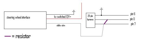
The diagram you get from PAC is very straight forward. Pin 6 connects to ground along with the black wire from the interface. The red wire goes to a switched 12V+ source. The white wire connects to a 150 ohm resistor (comes in the package..it measures at 145 but thats close enough!) and that same end connects to pin 7. The other end of the resistor connects to pin 8.

Here is my drawing on it, but I can't really get much more detailed than what you get from PAC.
 

Attachments

  • swc4d.jpg
    swc4d.jpg
    11.6 KB · Views: 589
This is the first I have heard about an antenna adaptor... does anyone know if the 05 needs one?

and thanks to tarheel and sbutz again... I think I've got this thing figured out. I'll let you know what happens after I do the work tomorrow night.
 
I appreciate your opinion, and for the most part I agree with you. I don't recall seeing any where in this thread stating that soldering was needed. I've used taps for years, but you'll never win an argument that a mechanical connection is better then soldering, provided the soldered connection has proper penetration.

I agree that taps are much quicker. The only problem I ever have with taps is that wire always seems to fall-out right when I'm trying to squeeze the tap :)

The PAC comes with a bunch of resistors... I think the 150ohm one is the only one with two green bands.... don't quote me.

Diagram looks about right.

Bluedevil if you search the forum you'll see others have discussed that there are two antenna wires plugged into the back of the factory unit. The FM is the standard Motorola plug, the other is about half the size. I believe the smaller plug is for AM reception. You will see what I mean.
 
A 150 ohm should be brown, green, brown.

If it just has 2 greens it may be 55ohm, (they should all have 3 bands though)
 
Thank you for correcting me.

I had to use some javascript resistor calculator when I was trying to figure out which was the right one.
 
I agree that soldering is better... and i wasn't completely regarding to this topic as the "needing" to solder topic, just the entire board in general.

Don't get me wrong, I'm not a half-ass kinda guy, but unless you are building a competition system where voltage drops and current is a HUGE issue, then you are merely putting way to much effort into an incredibly simple install.

I've been installing for nearly 4 years and working in a premier area with mainly Lexus, BMW, Mercedes...etc... and if its not those its always a newer car. But IDC what car it is, you'll rarely find me or anyone else in our shop soldering connections with the exception of a remote start here and there when we're bored enough to do it that way.

The taps I'm referring to are different from the ones I'm thinking you might not be having good luck with. The ones I suggest are commonly referred to as t-taps. The come in red, blue, and yellow. Red used for smaller wires and goes up to yellow which is used for anywhere up to around 10 guage. Here is a link to a picture I found...

click me!
 
I agree those t-taps in the link are better. It just always seems they are harder to find when I need them.

I think most do-it-yourself people in the forum don't mind taking the time to solder the connections on their own vehicles. I know that is the case when I do any sort of install.

In an installation shop where time is money, I can see using taps. I don't think there is anything wrong with taps.... I'm not judging.

I appreciate you taking the time to input your opinion and experiences as an installer.

Thanks!
 
lemme get back to this antenna adapter thing...

since I listen to a fair amount of sports talk radio, I use AM frequently so I think I may need some sort of adapter. Anyone else have experience using just one of the antenna plugs in an aftermarket HU? Is the difference non-existent?
 
I'm not positive what the adapter is. I can't seem to get a straigh answer out of anyone.

If you search on Crutchfield for Item #12040NI10. This adapter looks like it will work. I'm not sure if anyone else can confirm if this will work. It is only 13 bucks, I may order it just to try.
 
It will not work. If you look closely you can see the reflection for 2 slots in the end of the antenna. The nissan antenna looks like the picture I posted below... Has 2 prongs and a clip on top, you can just barely see the tab on the adapter because its being blocked by the crutchfield logo.
 

Attachments

  • nissan.jpg
    nissan.jpg
    2.1 KB · Views: 256
Thats too bad... I was hoping that was the right one.

What would you do if you were doing an install at work? Do you know what the proper adapter is?

I had one installer tell me he has spliced the two antenna wires together but found that reception quality actually dropped.
 
I just completed my install... sort of and using just the larger of the two antenna plugs and hooking up the power antenna wire gave me a solid signal. So good news on that front.

However... I thought I hooked everything up correctly, but the steering wheel controls aren't working at all. I soldered the white wire above the plug, soldered the power to the ACC power on the radio harness, ended plugging the resistor into the 7 and 8 slots on the plug (with the white wire coming from the 7 wire), and tapped into the ground above the plug. Yet nothing.... did I miss something on the ground end? Should I have soldered onto the ground wire something that ties into the ground on the radio harness? Maybe some tips for using the resistor?

Since the PAC didn't light up after I started the car (per the directions) I assume it didn't work.
 

Members online

Forum statistics

Threads
278,310
Messages
3,554,077
Members
248,016
Latest member
Advally Service

Trending content

Back
Top